This assembly guide starts from constructing the standing desk, before progressing to mounting the robot on the desk and installing various other components to the platform. There are a number of design options/variations for the mobile platform, these are discussed under each of the major headings.
Table of contents
Building the Desk
It is expected that you have procured a standing desk similar to the one listed in the shopping list. The desk you procured should be accompanied with an assembly guide please follow this guide to construct your standing desk.
Important: at this stage, don’t attach any extras such as trays and/or cable management items to the bottom of the desk as we will be installing components to the underside of the table in future sections of the guide.
Mounting Robot on the Desk
Option 1: Breadboard Base
A flexible option for mounting the robot on the desk is to bolt a set of rails to a breadboard and subsequently mount the robot on these rails. The main advantage of this form of mount is that it is possible to reposition the rails and mount position of the robot.
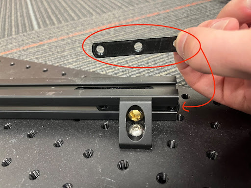
The first thing we will do is construct the rails upon which the robot will be mounted:
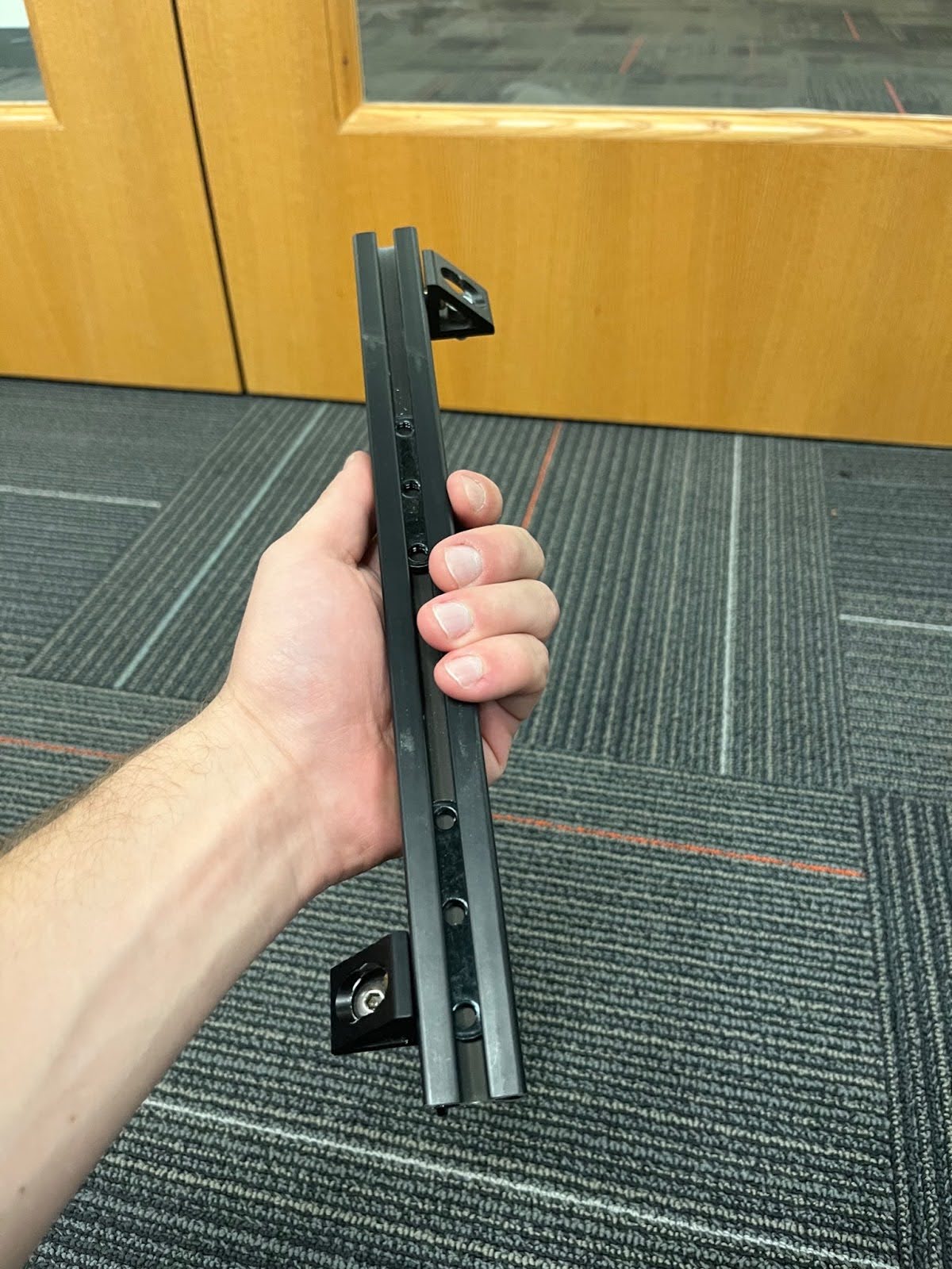
- Take a 1 foot aluminum bar, and slide the bracket circled in red in the below image (yours may look different) into the left and right side of it.
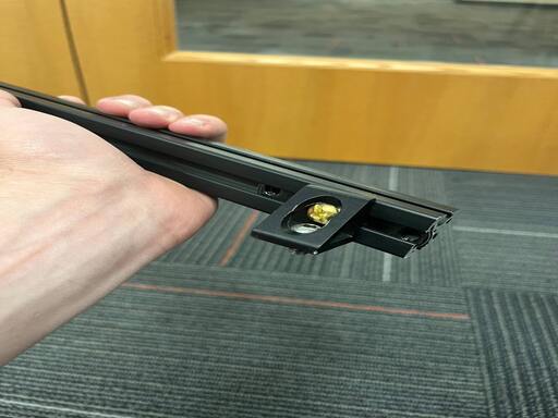
- Put two of the screws (1 cm long, 5mm wide) into a corner bracket and loosely screw one side into the bracket within the 1 foot aluminum bar on either side.
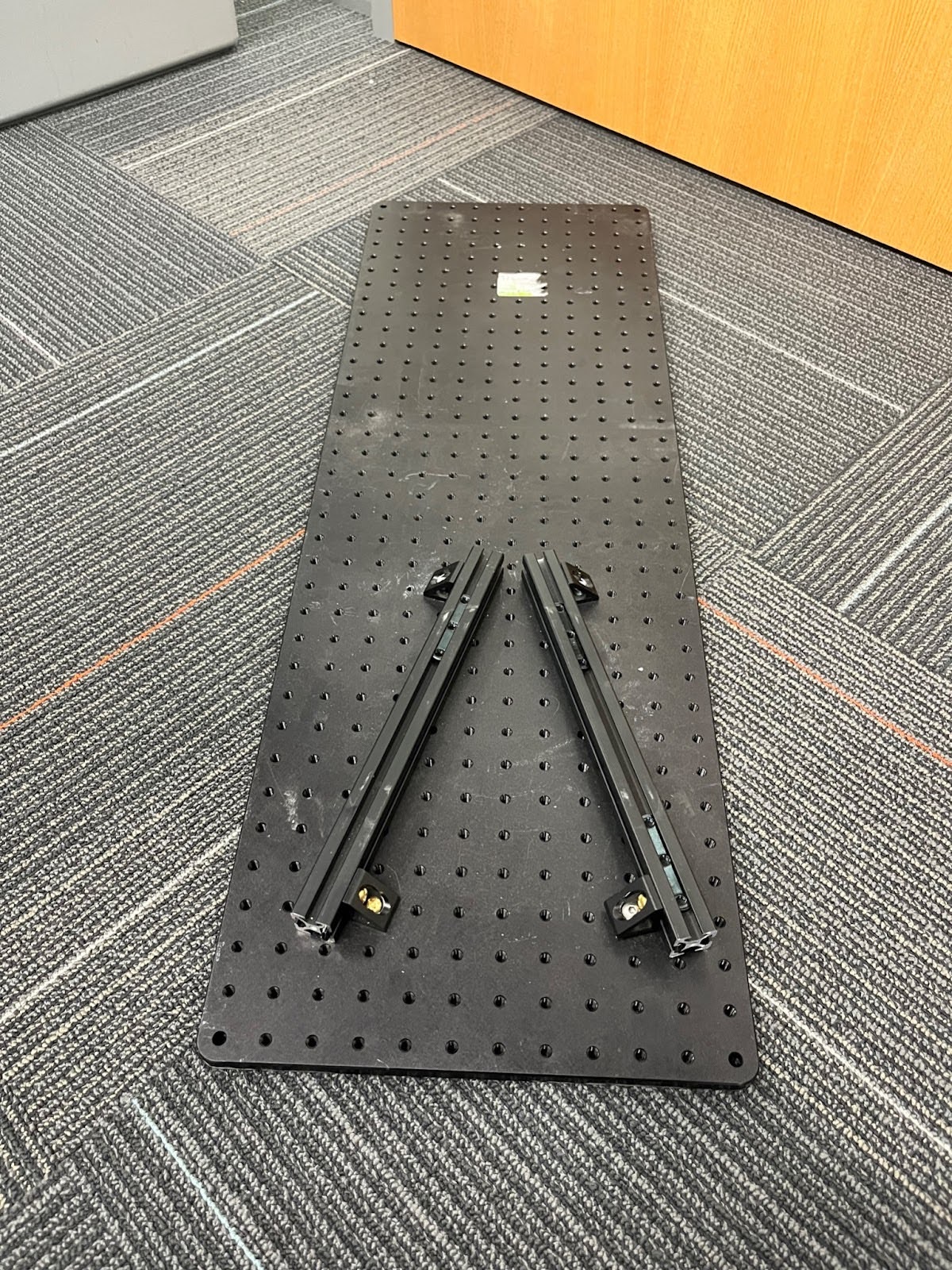
- Use this technique to create a rail that looks like the rail in the third image below, and another that looks is a mirrored version of this (ie. one corner bracket in the upper right and one in the lower right)
Next we will mount these rails on to our breadboard:
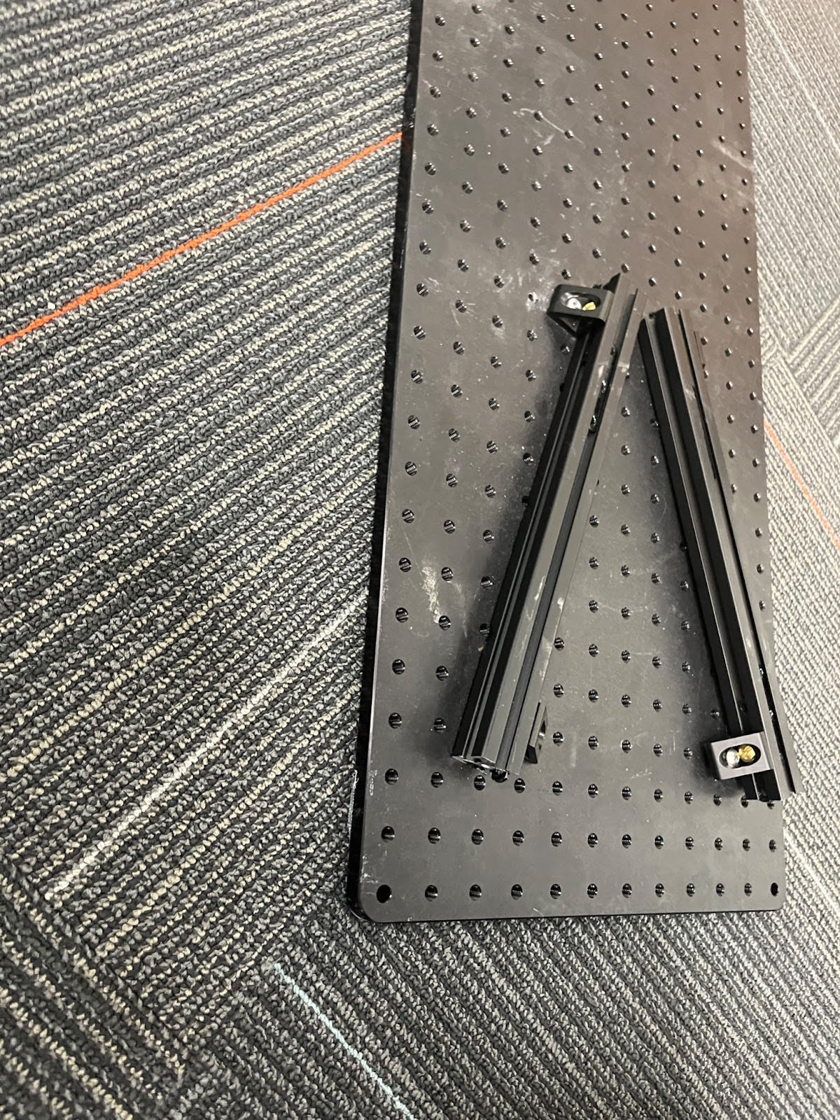
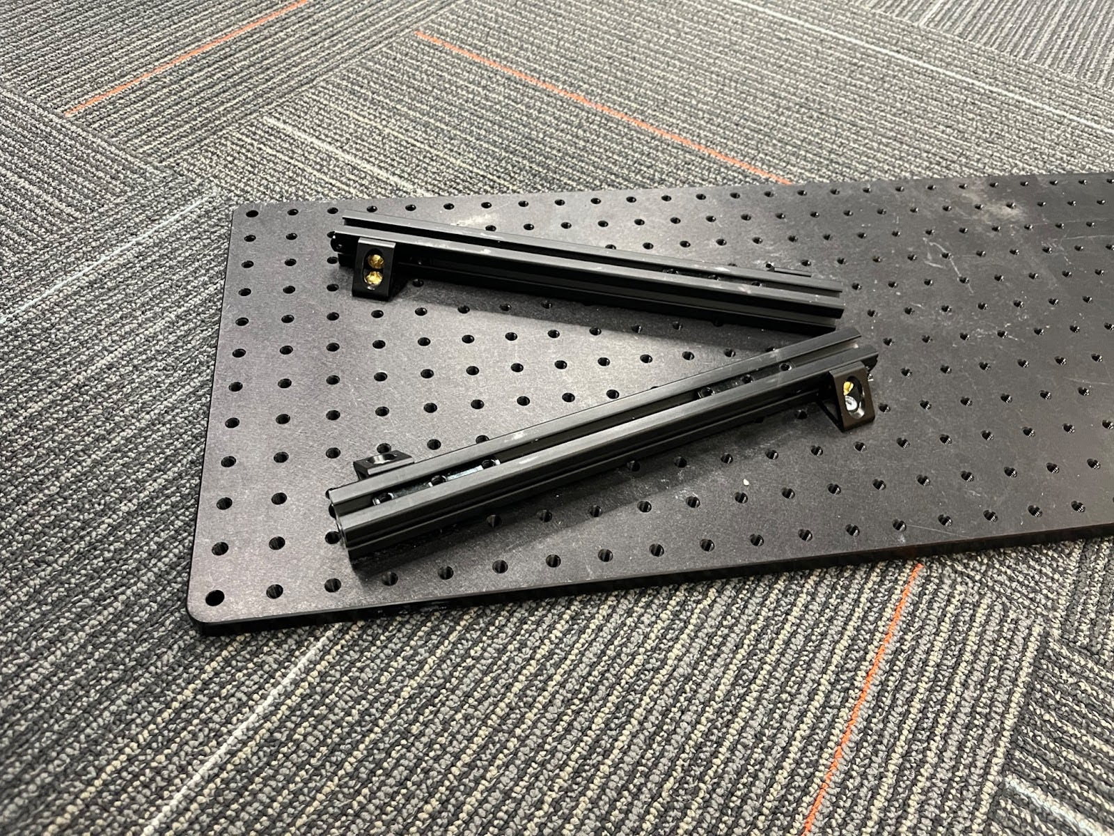
- Screw the aluminum bars into the breadboard in the configuration shown below. Unfortunately it’s not possible to achieve perfect symmetry when bolting the rails to the breadboard. Feel free to nudge the centering a row or column over for diversity (ex: configure it so there are two holes on the right instead of the left).
- Make sure this is one hole between the bars on the top, and 5 holes between the bars on the bottom
- Hint: to keep the screws from colliding when screwing them in, (lift up the bar before screwing so the screw sits at the bottom. (Insert picture)
- Slide two brackets into the top levels of each aluminum bar, we will be using these to attach the Franka.
Now we mount the robot:
- Align the brackets with the Franka screw holes, and loosely screw the robot to the base.
- If you’re using an FR3, use the ⅝” long screws to mount the robot instead of the original screws.
- Once everything is loosely screwed in, tighten ALL SCREWS until everything is entirely fixed!
Next place the breadboard on your standing desk:
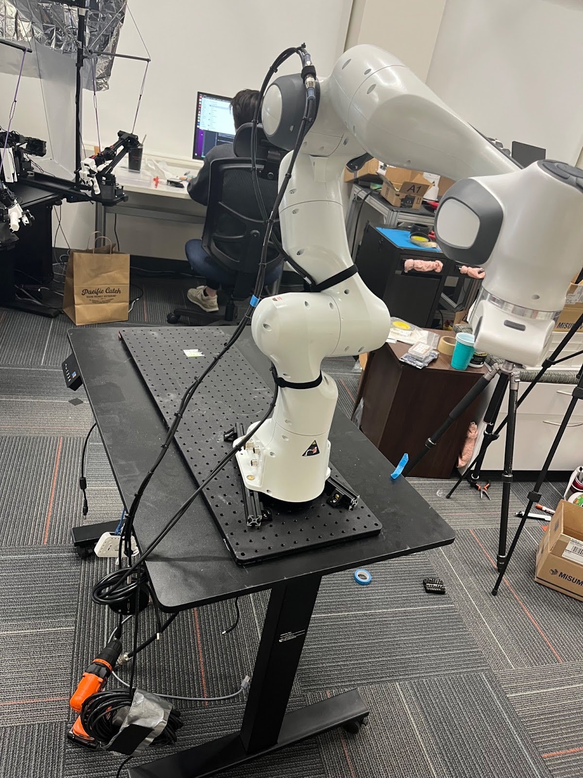
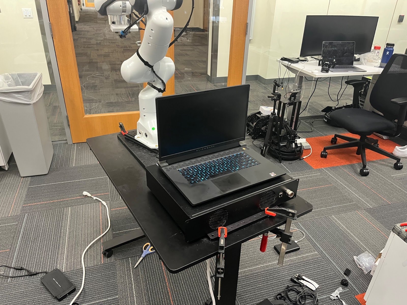
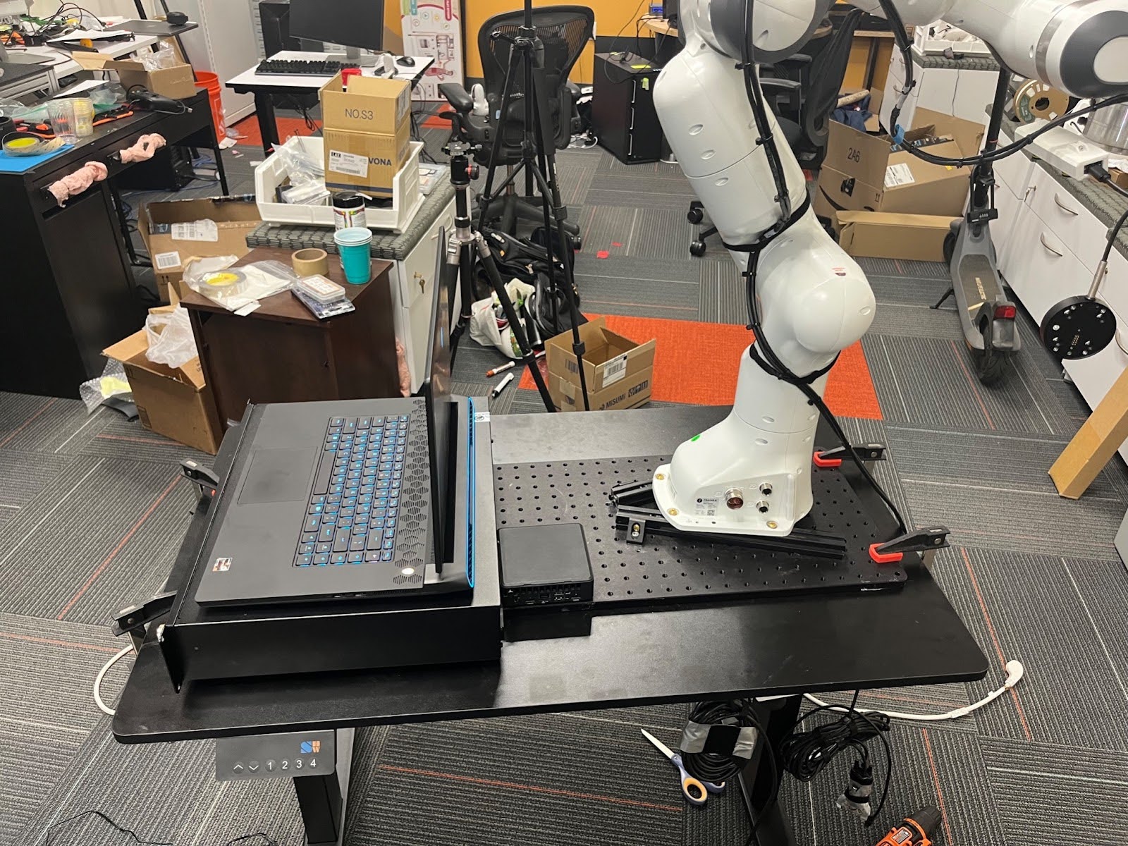
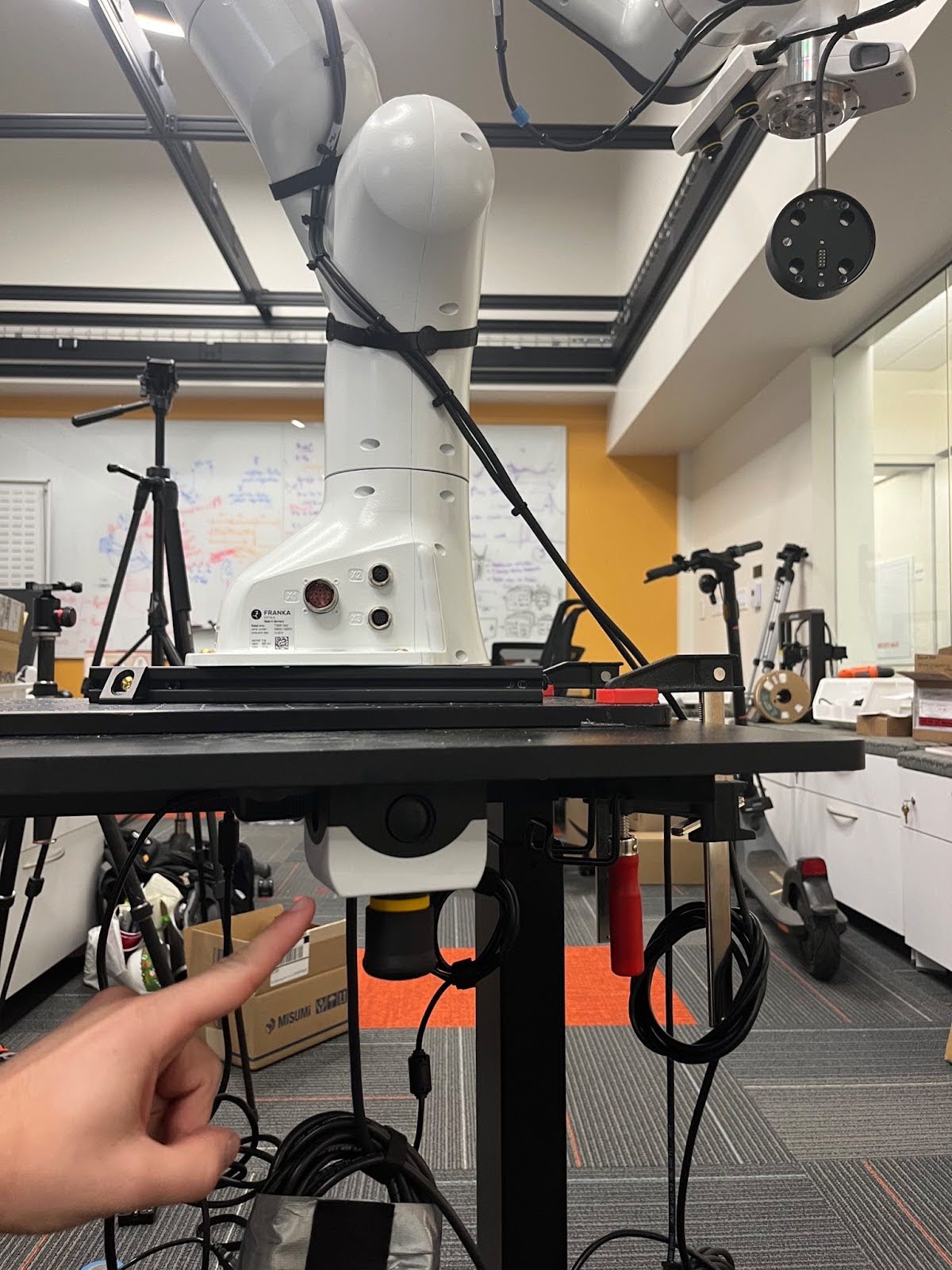
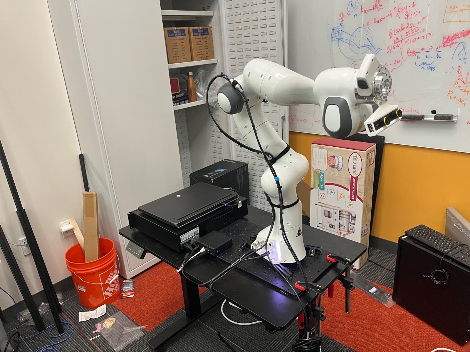
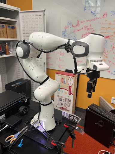
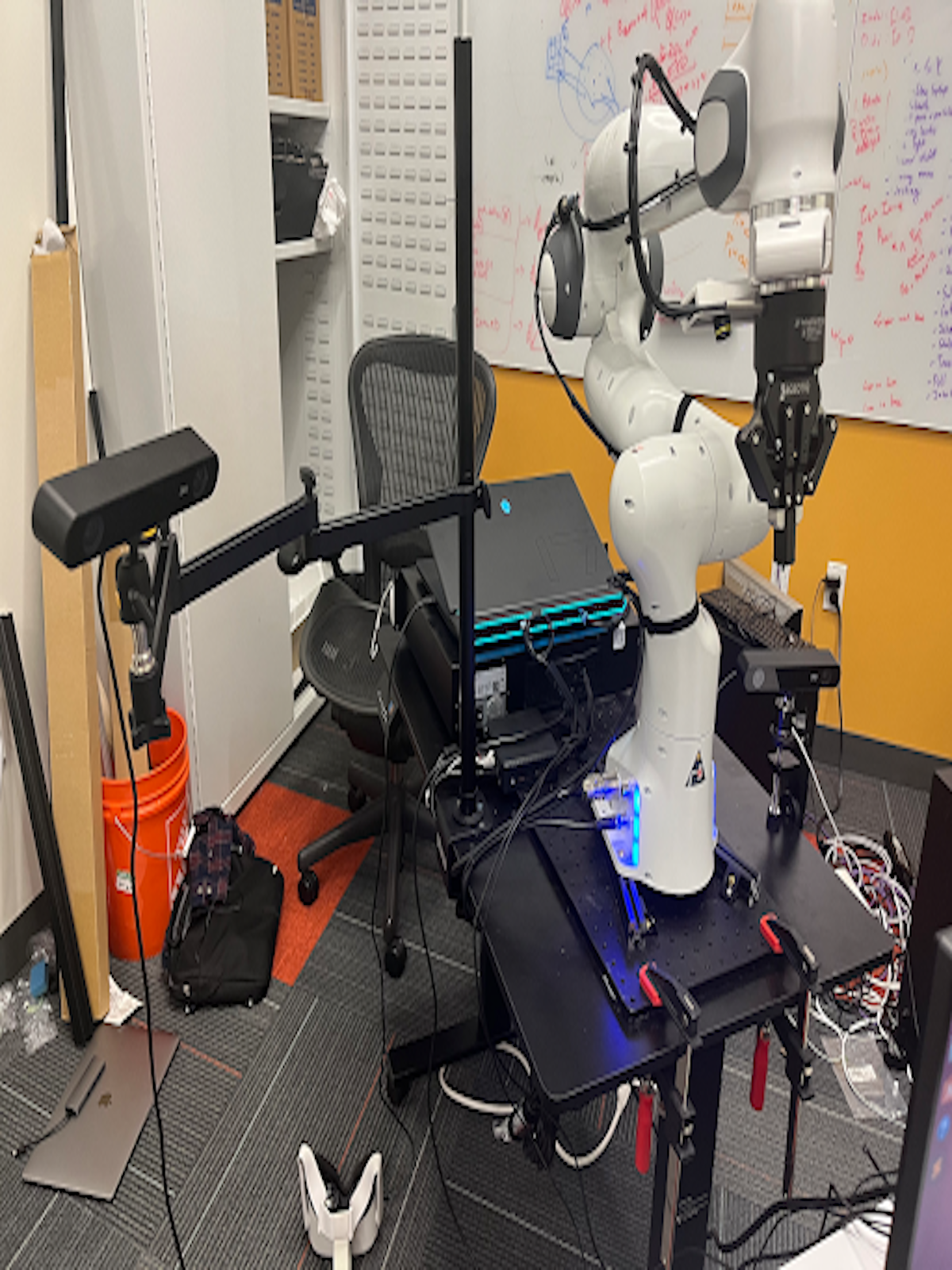
- Center the broadboard as much as you can on top of the desk. It should look roughly like the below image (minus the wires on the robot):
- Important: Make sure that the franka is facing the side without any desk protrusions. An example of a desk protrusion is the height adjuster on the recommended desk (seen on the back, left side of the desk below).
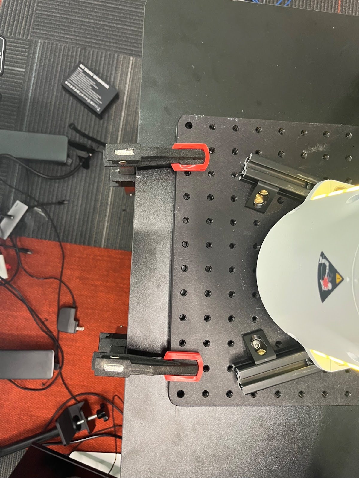
- Use four clamps (two on either side) to connect the breadboard to the desk.
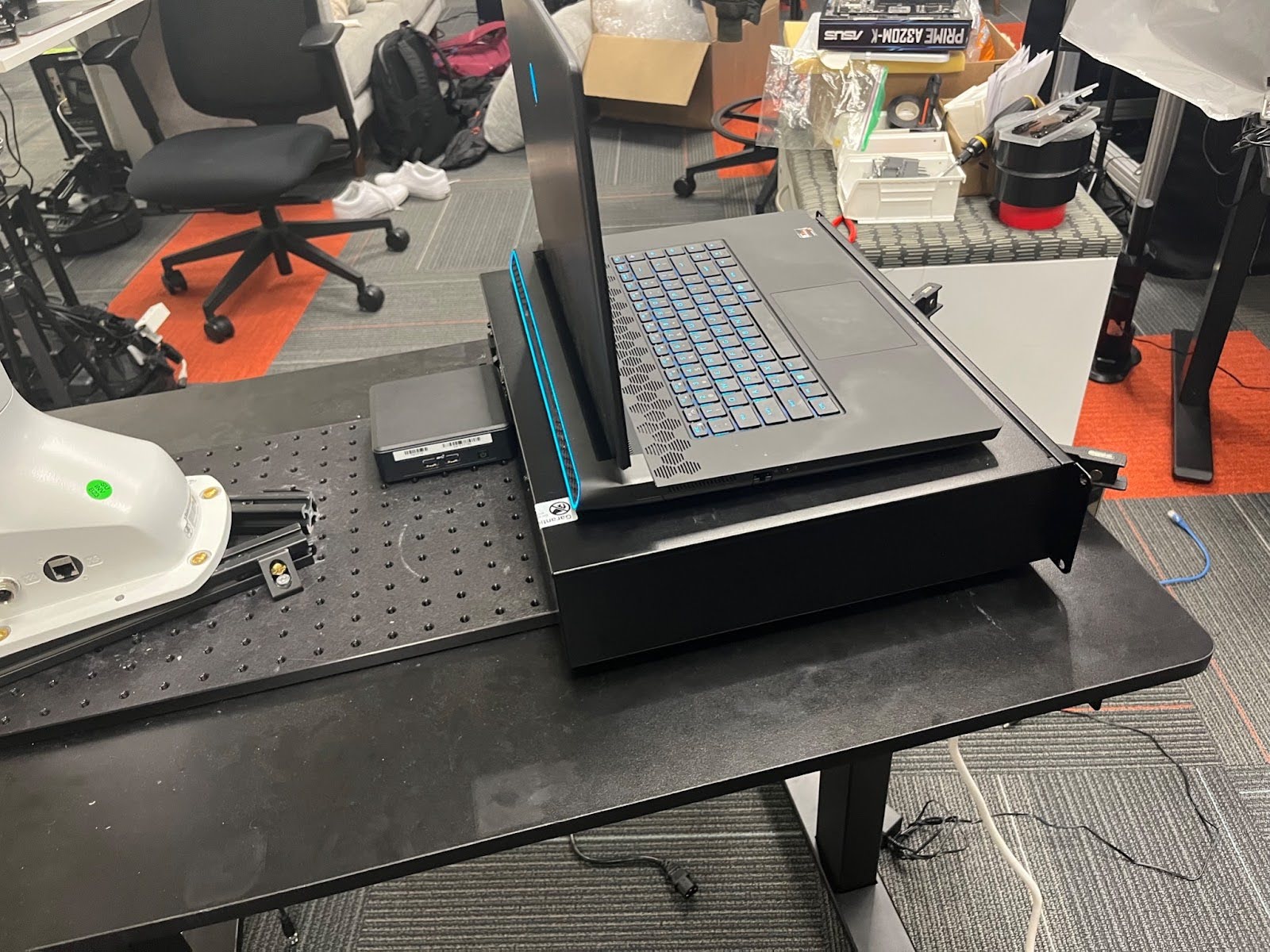
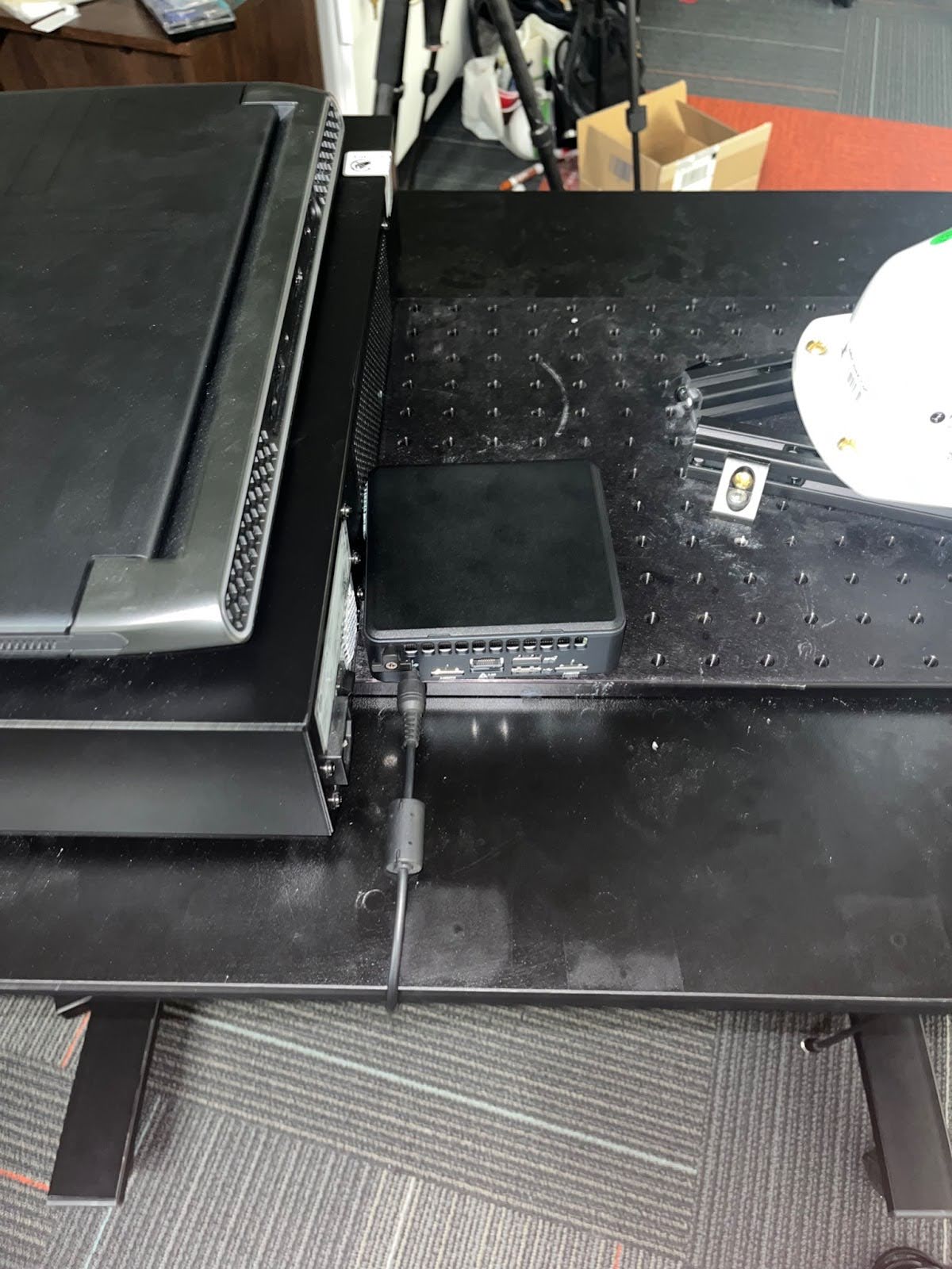
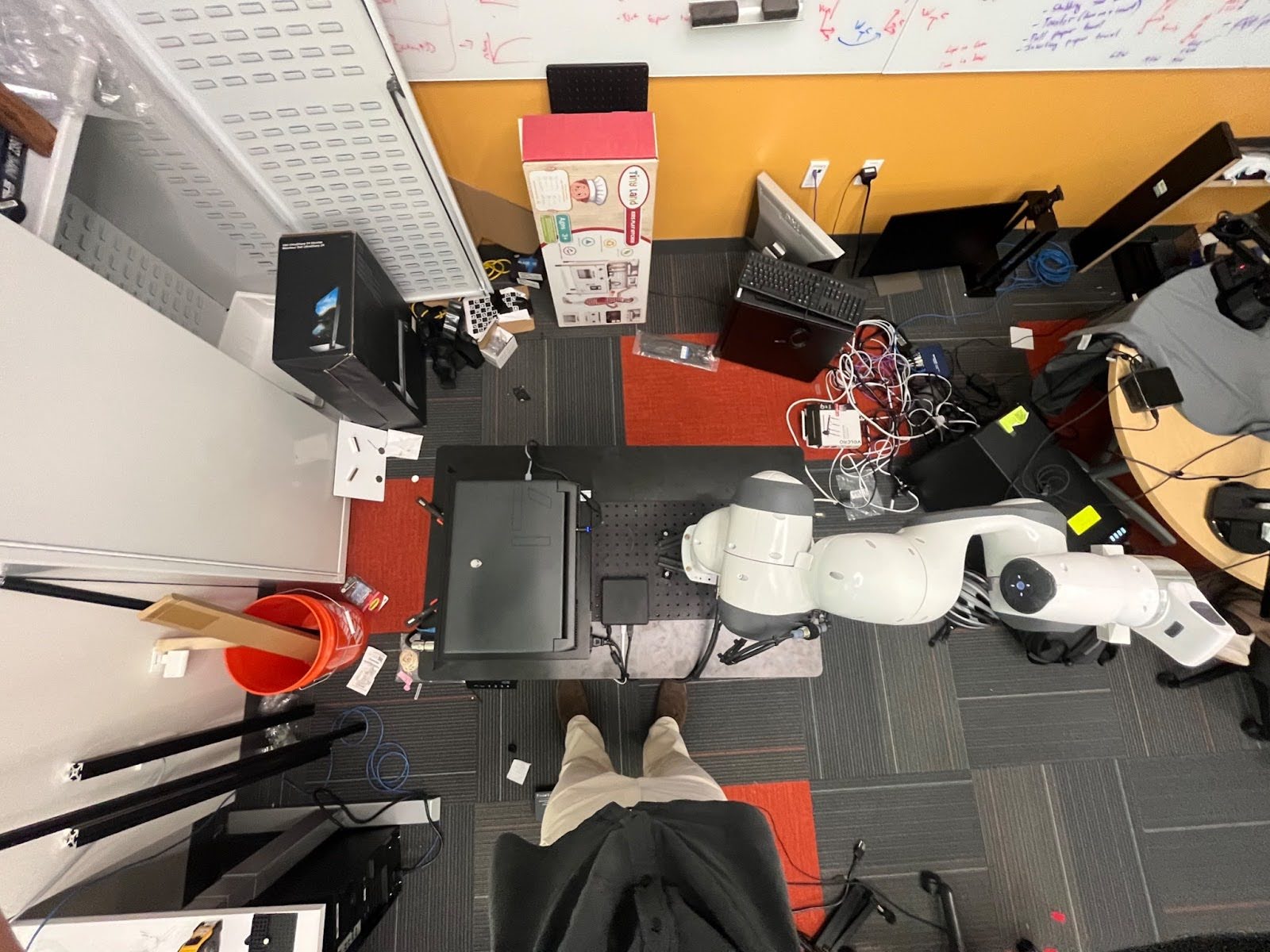
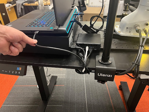
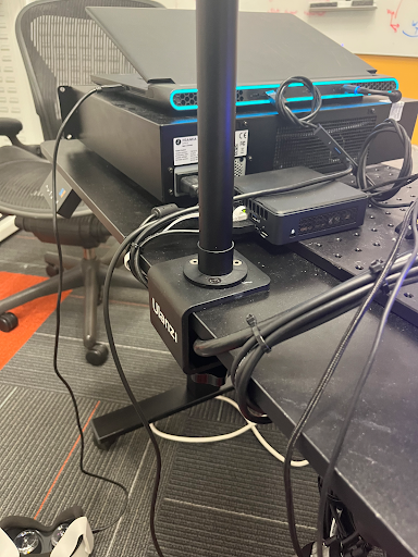
- Place the Franka power box, laptop, and NUC in the following configuration:
Mounting Additional Components on the Desk
A requirement of the DROID platform is that it can easily be transported from one location to the next. In this section, we outline configurations for components on the desk in a way that enables greater ease of transportation. Some important points to this end:
- Throughout this section, take time to organize loose wiring with zip ties, velcro strips and/or sticky hooks in order to keep your desk organised, it is important that wiring be as permanent as possible.
- Getting rid of as much loose wiring and making things as organized as possible during this step will make your life much easier later on!
- Cameras are mounted to the sides of the desk ensure your organise wiring such that you keep space open for moving around the camera mounting location!
- When this doc discusses the location under the desk, we will define forward using the robot. For example “Attach X to the back right side of the desk” means with respect to the direction that the robot is facing.
- Be generous with the amount of industrial strength velcro you use on power boxes, they can be heavy!
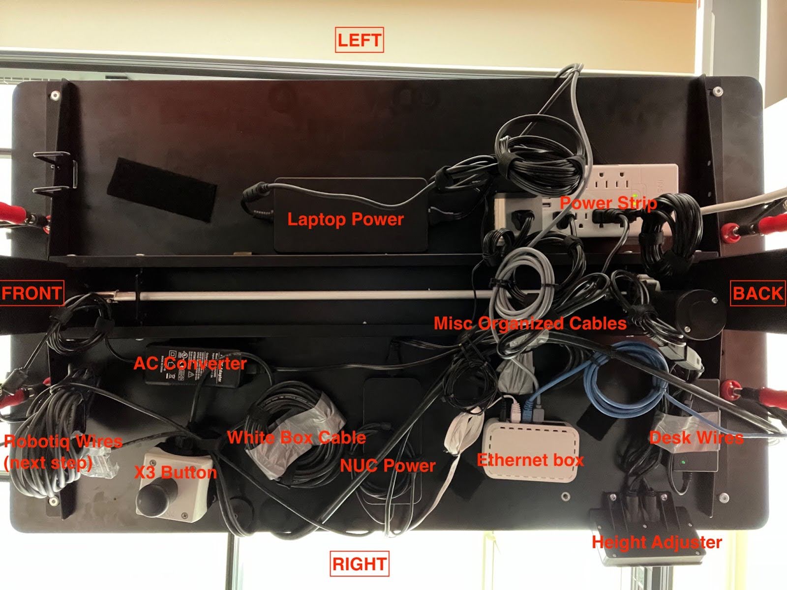
- Scroll down to see what the end product should look like. It would be a good idea to frequently come back to these images and compare.
Option 1: Configuring Components on Underside of Table
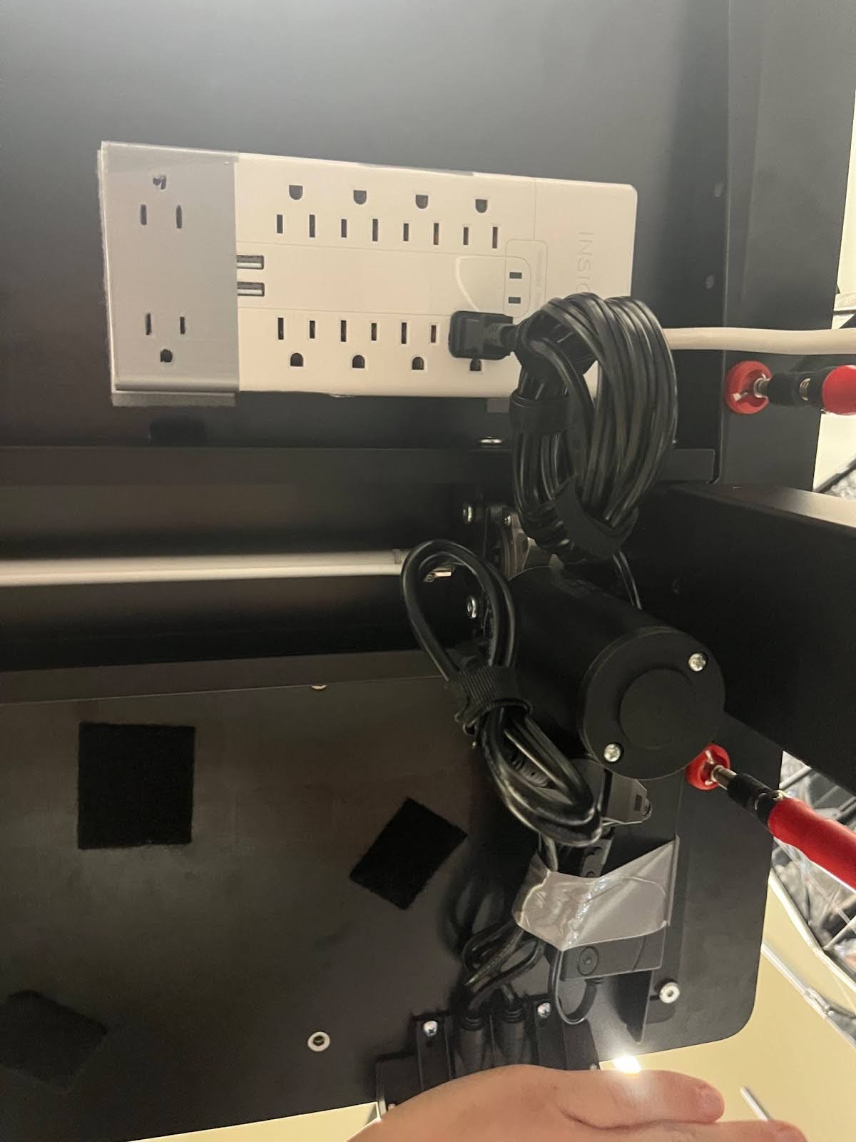
- Use velcro to attach the large power strip to the back left of the desk.
- Make sure you face the protruding wiring towards the back of the desk.
- Use velcro to attach the standing desk power box to the desk, organize the loose wiring, and plug it it into the power strip:
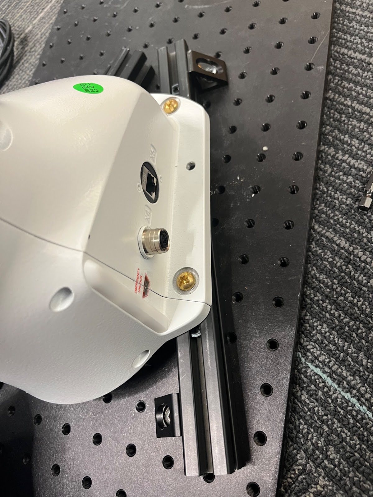
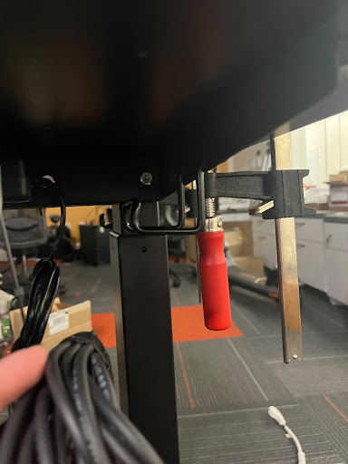
- Use velcro to attach the Franka emergency stop (the white button) to the the bottom of the desk. Attach it on the right hand side directly under the Franka towards the outside of the desk so it is easily accessible. Face the protruding wire towards the center of the desk to keep it from protruding:
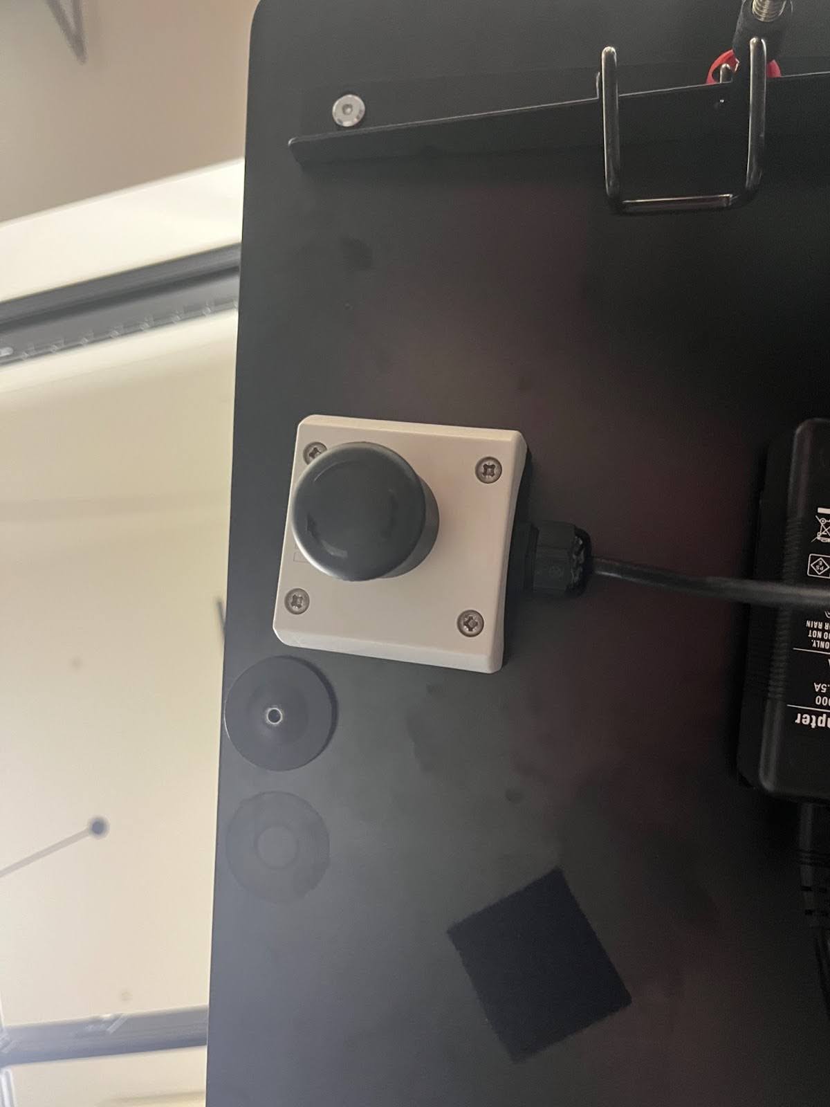
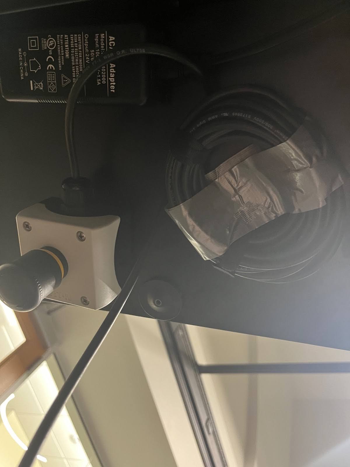
- Connect the emergency stop wire to the X3 port on the Franka
- Use Velcro to attach the power unit for the Robotiq gripper. Face the built in wire towards the Franka. Plug the other side in and connect it to the power strip.
- Use Velcro to attach the power unit for the NUC directly under it (middle right side of the desk). Face the built in cable towards the outside of the desk. Plug in the other side and connect it to the power strip.
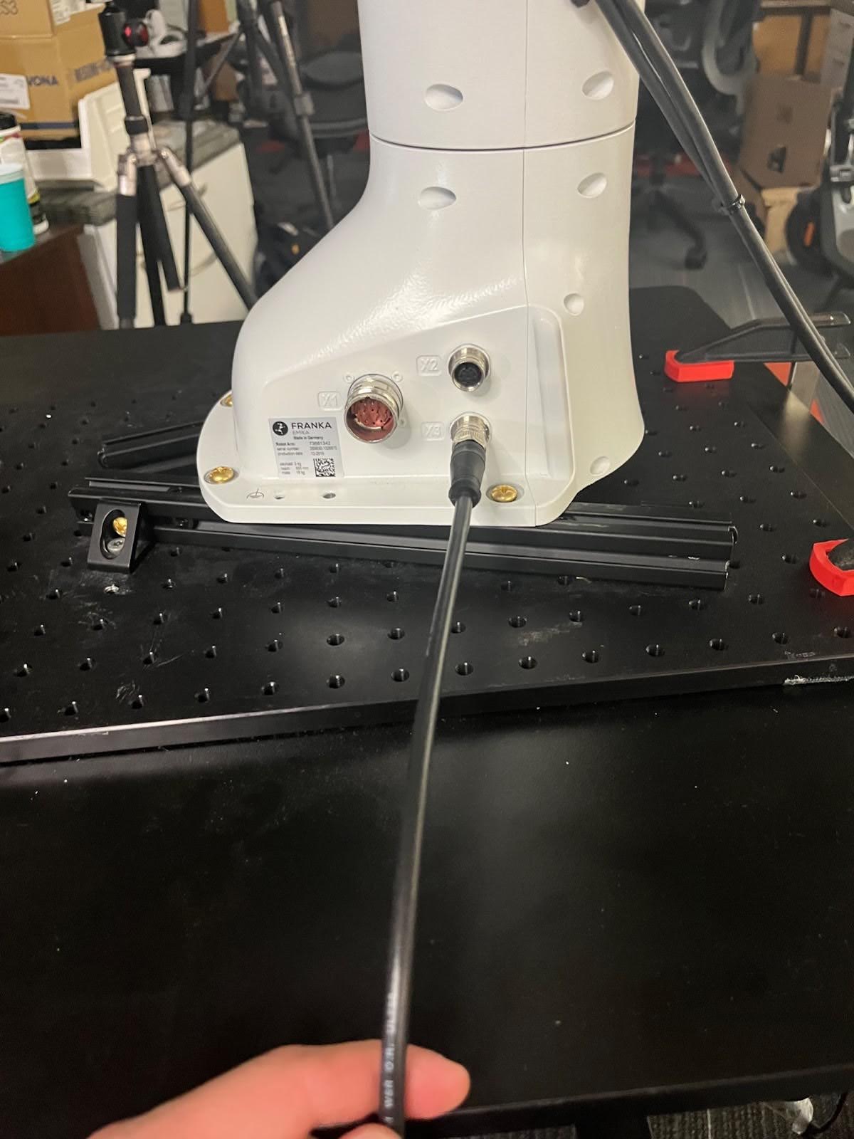
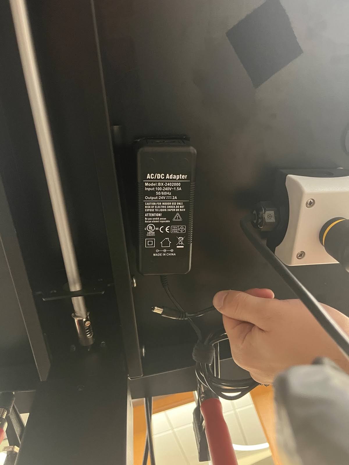
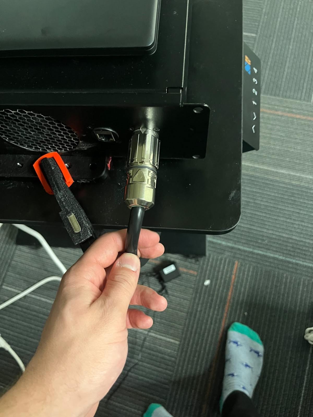
- Connect the Franka power box power cable to the power strip:
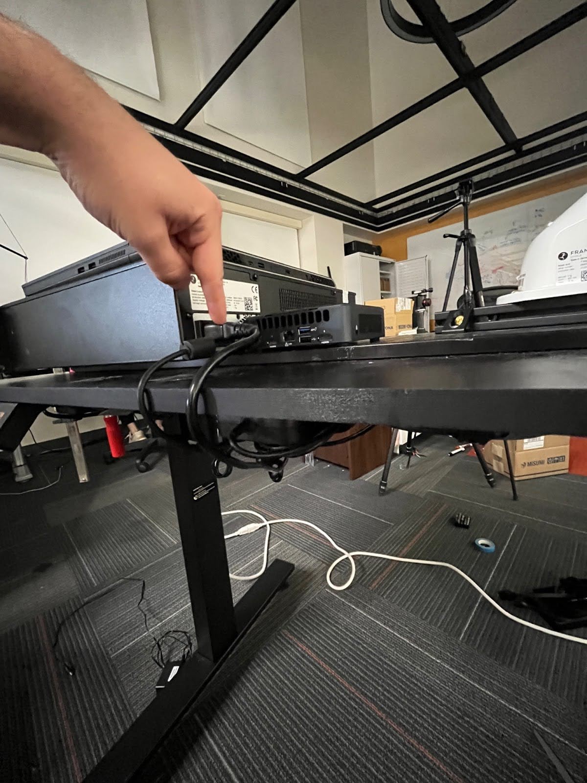
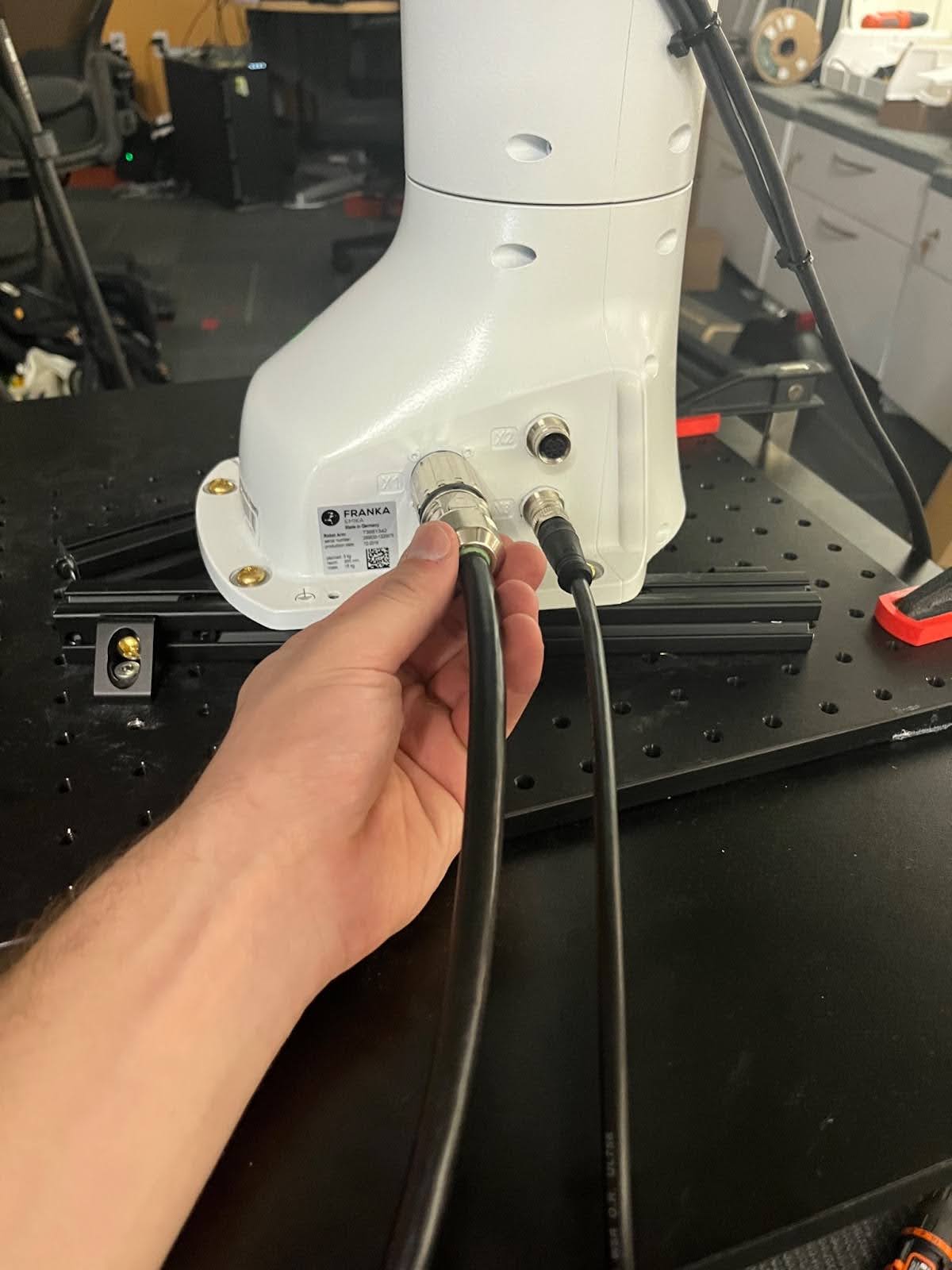
- Connect the cable from the X1 port on the Franka to the power box
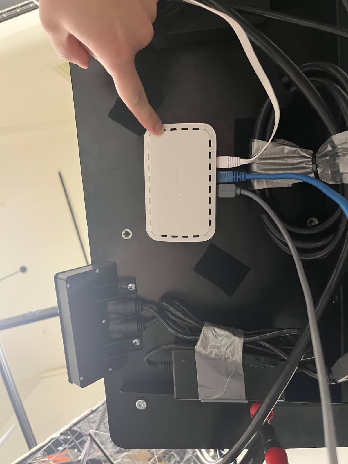
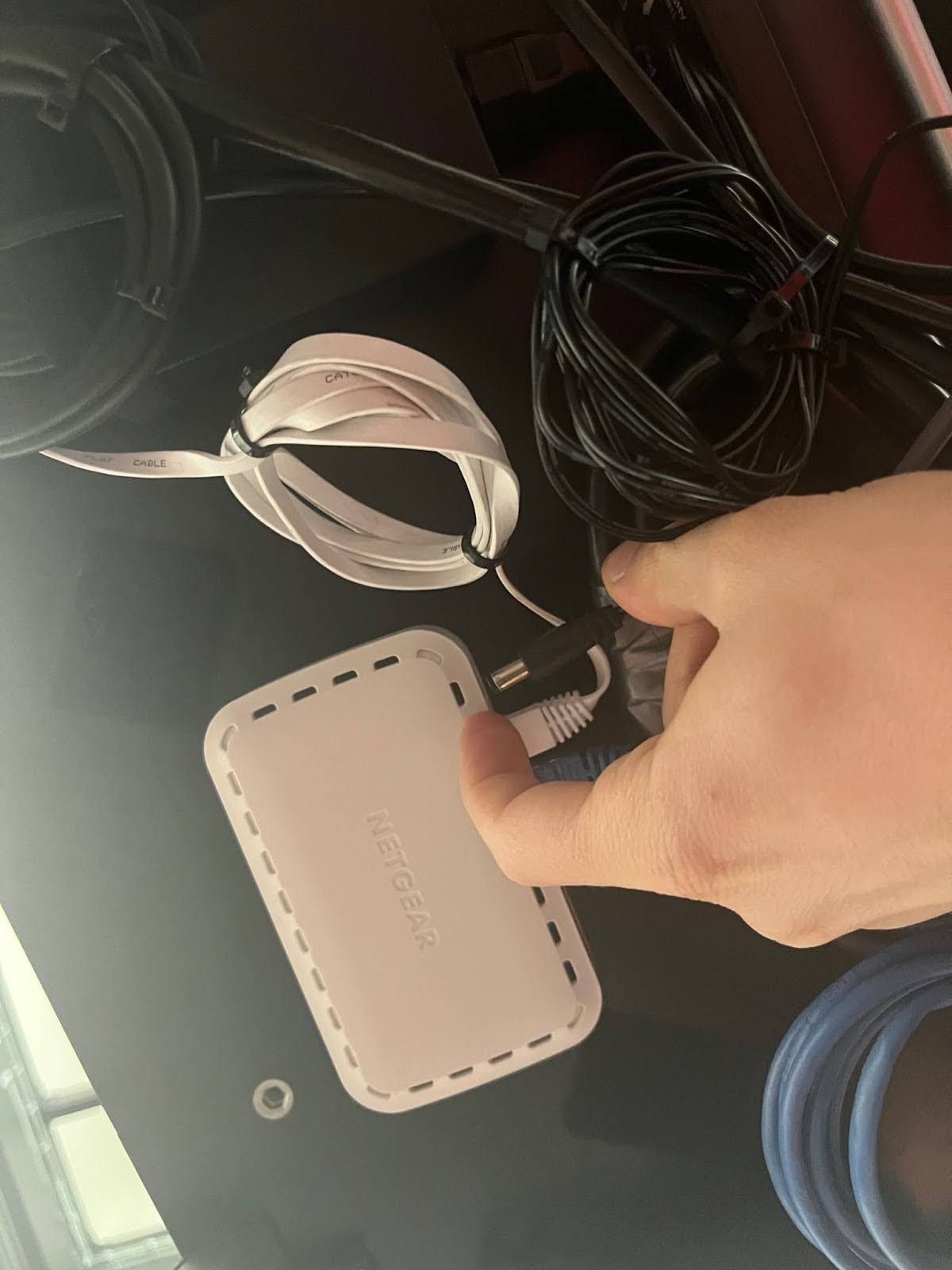
- Use Velcro to attach the Ethernet switch under the desk on the back right hand side of the desk (under the Franka control box).
- Connect and organize the Ethernet switch power cable, the switch to Franka power box ethernet cable, the switch to NUC ethernet cable, and the switch the laptop Ethernet cable.
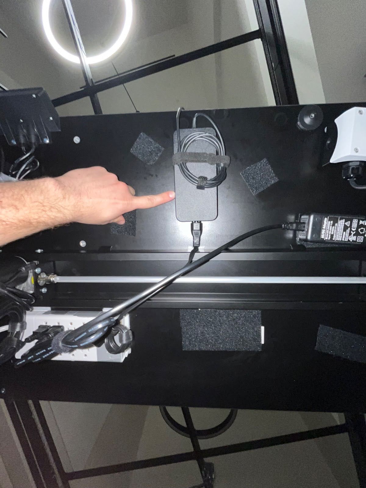
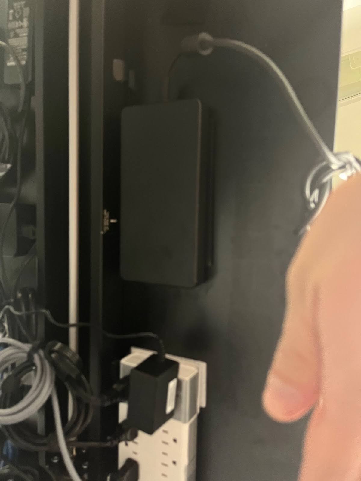
- If you’re using our recommended laptop, use velcro to attach the power box to the bottom of the desk on the back left side, with the built-in cable facing the robot. Plug in the detachable cable and connect it to the power strip.
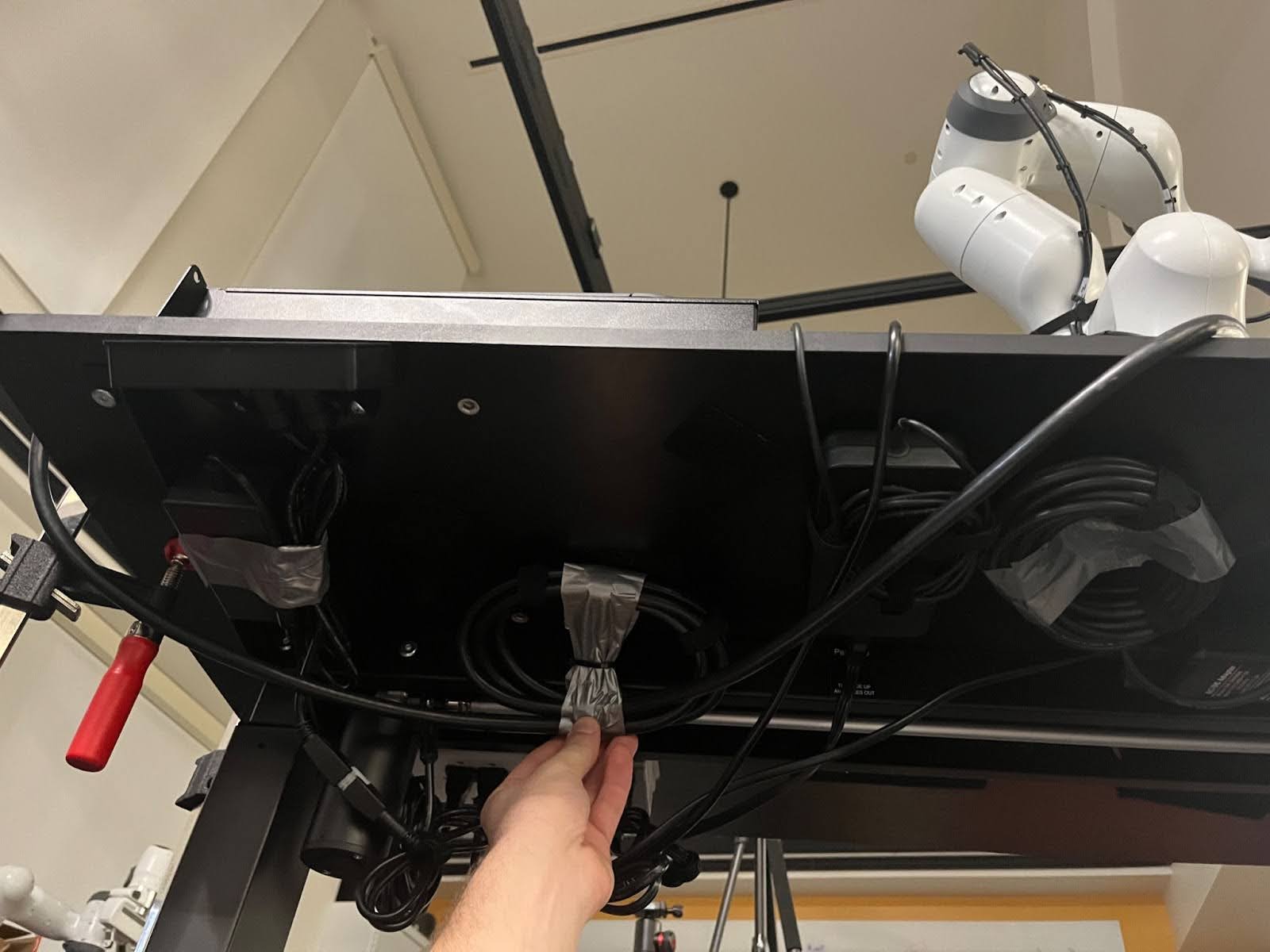
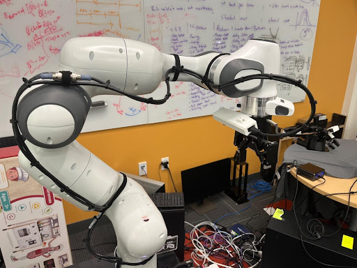
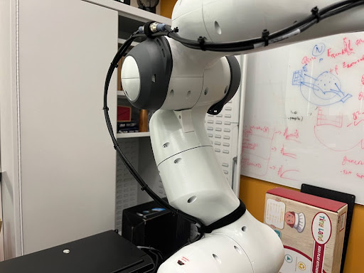
- You’re done! Your setup should look something like the photos below. Ignore the wires going down the robot, and the hand camera, you’ll set those up later.
- Before proceeding, please set up your robot with the Franka software as we will need to put it into zero gravity mode for the next step. Once you’ve done this, familiarize yourself with the text in the “Powering Up Franka” section of this document.
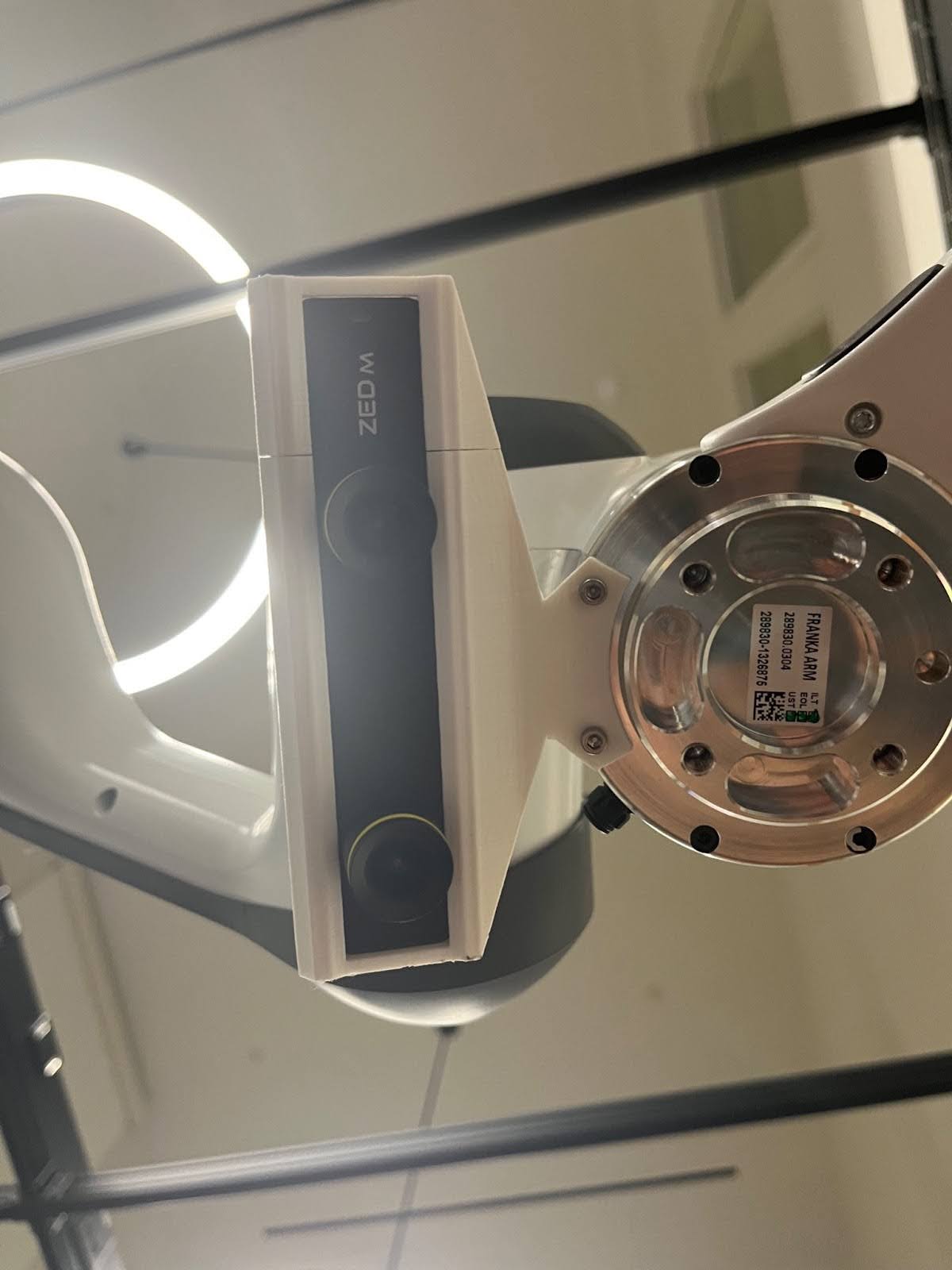
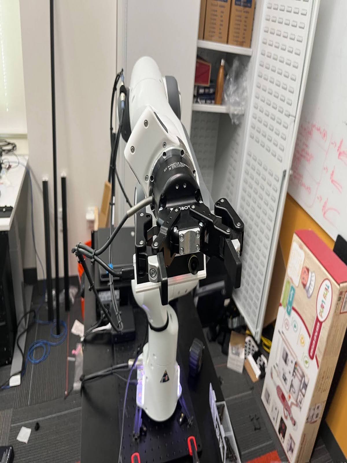
Mounting Hand Camera on Robot
In this section, we will specify how to mount the zed mini camera on the Franka robot arm.It will be easier to perform this part of the assembly with the Franka robot arm in a position that you have easy access to the last link of the robot (often referred to as link8).
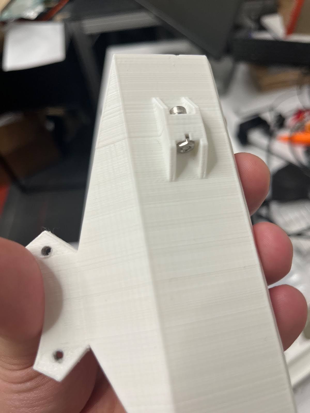
- Secure the camera in the custom mount specified in the shopping list, insert a nut into the hole on the back of the mount. Insert the 10mm screw on the other side, and tighten the screw in until the attachment is tight.
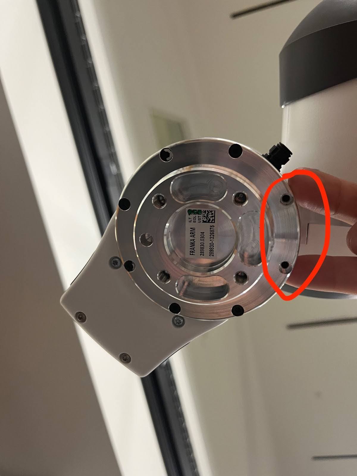
- Remove the back two screws in the Franka wrist:
- Use 30mm screws to attach the hand camera to the gripper (Important: these are different from the default screws that come with the arm).
Mounting Robotiq Gripper on Robot
In this section, we will first prepare the Robotiq gripper wiring as it is non-trivial. Following this we will specify how to mount the gripper on the arm.
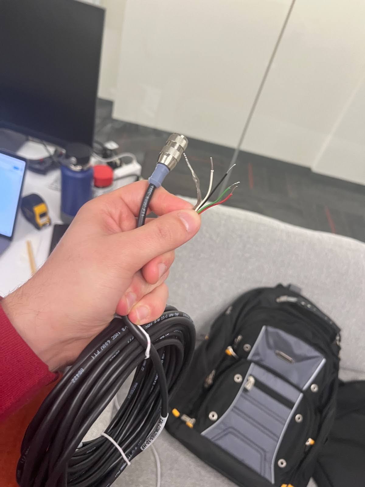
Preparing Wires
- You should have a thick cable that has 5 exposed wires colored red, black, white, green, and silver. We are going to connect them to ports as demonstrated in the below images.
-
To connect these wires into these ports, you need to cut off some of the rubber to expose ~5mm of metal thread. Then, unscrew the bolts up top to create some space for the metal threads. Jam the metal threads into the empty space, and screw the bolts tight again on top of them. \
-
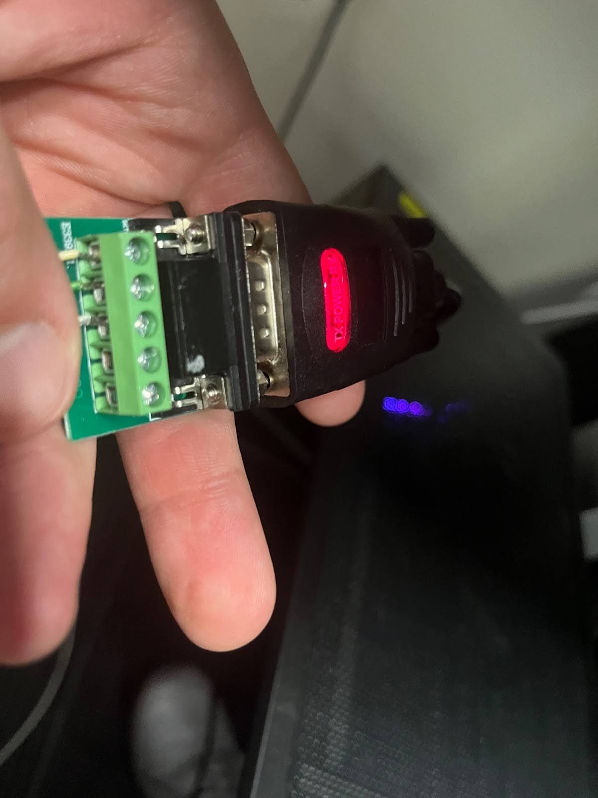
Connect the wires as follows:
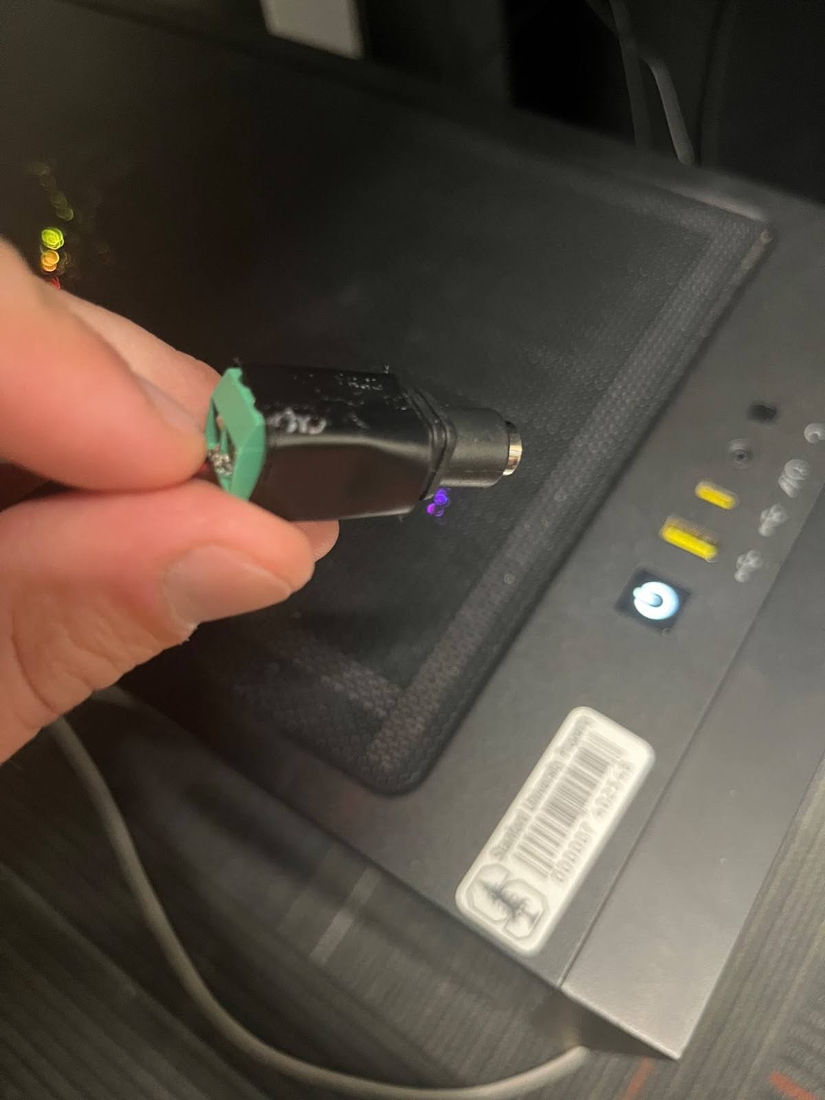
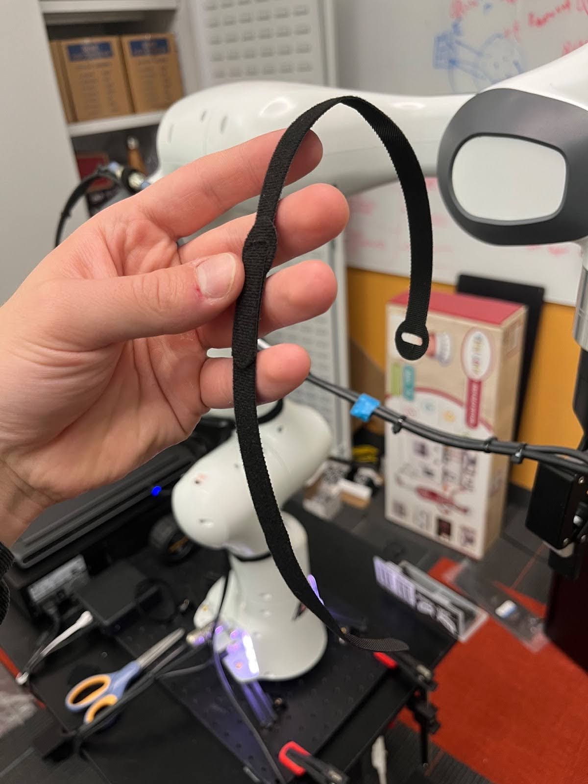
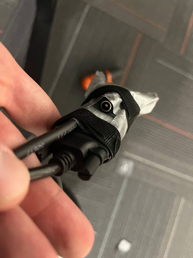
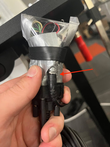
- Cover these wires with a plastic of some sort to keep things from pulling on them. Then, use a Velcro strip to tightly bound everything together so that there is no pressure on the loose open wires. Otherwise, they will come loose and the gripper will stop working. Make sure to leave the outlet uncovered.

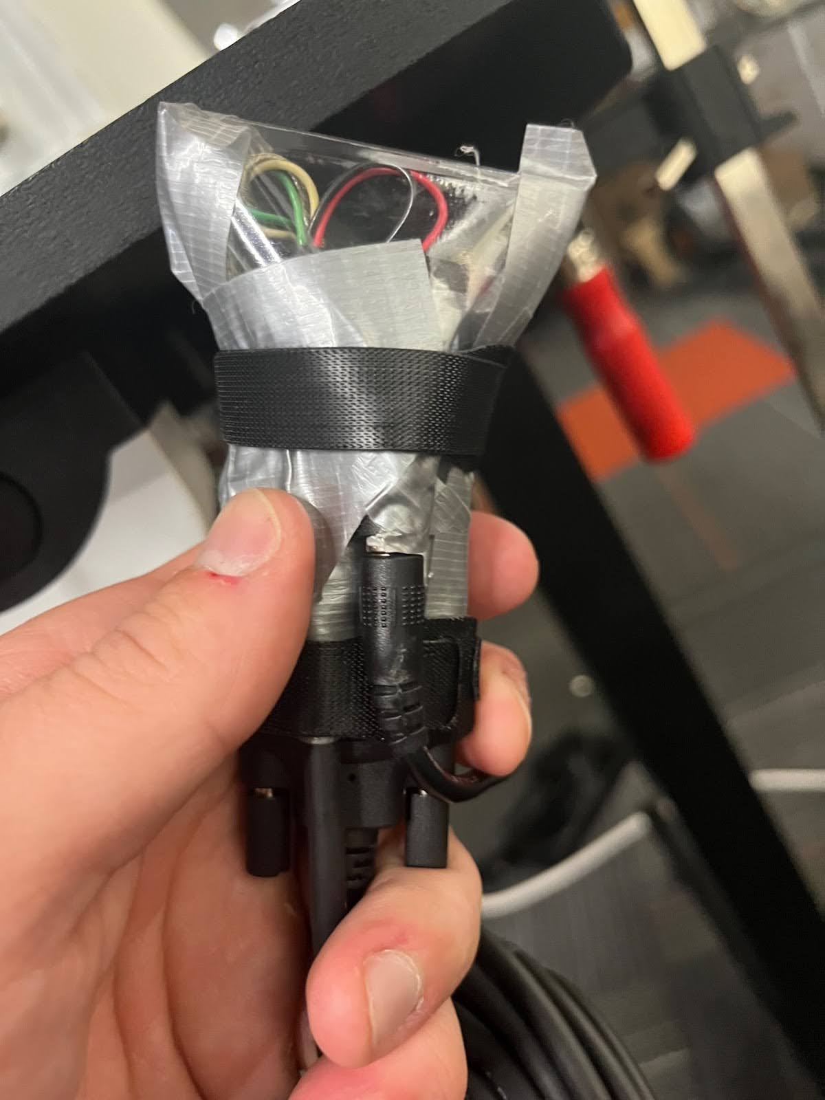
- Try connecting the gripper to the AC cable. Make sure that the gripper light shines red.
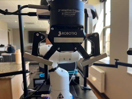
Mount Procedure
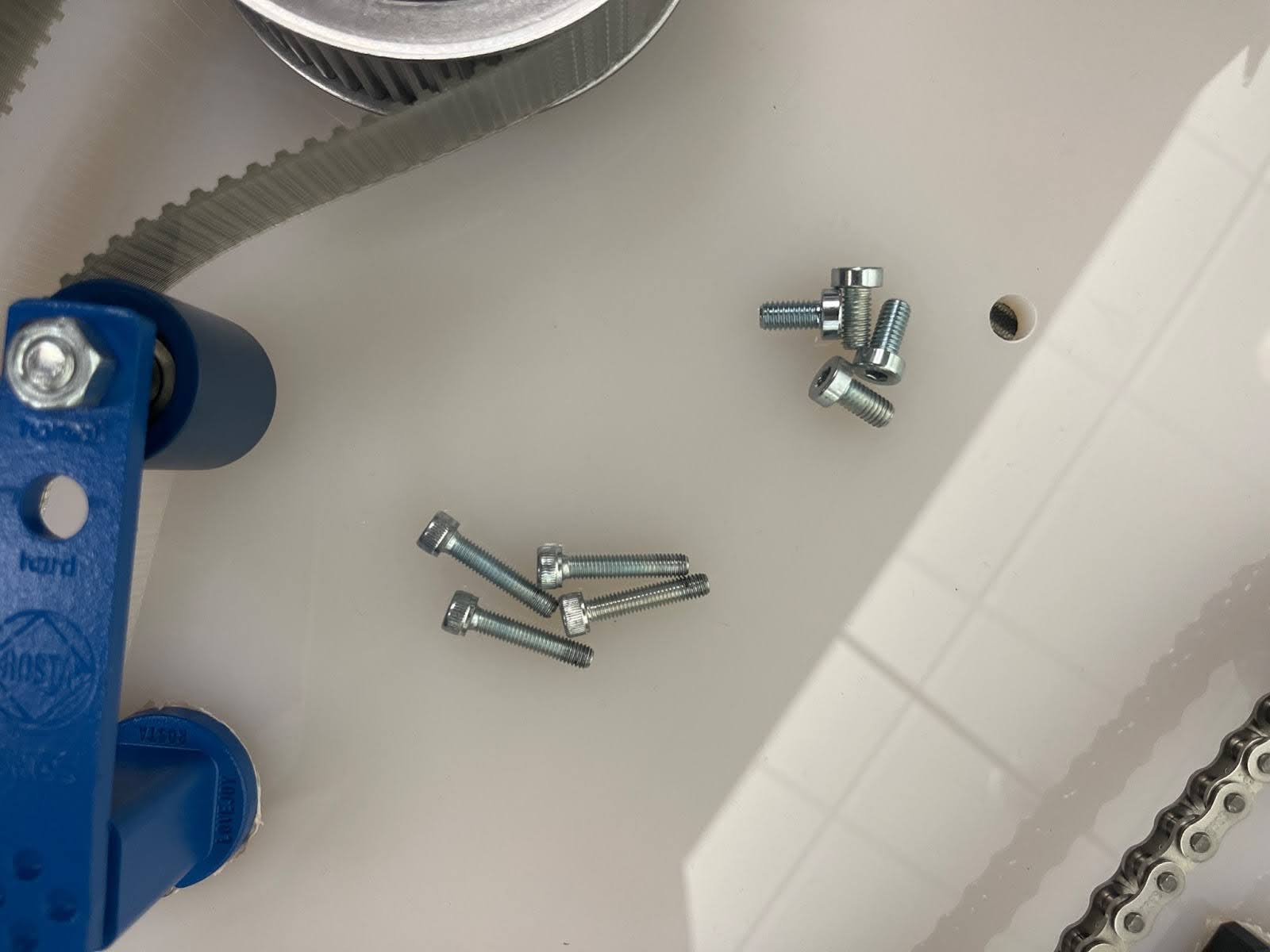
- To start, you should collect these screws from the box (4 x 10mm, 4 x 30mm)
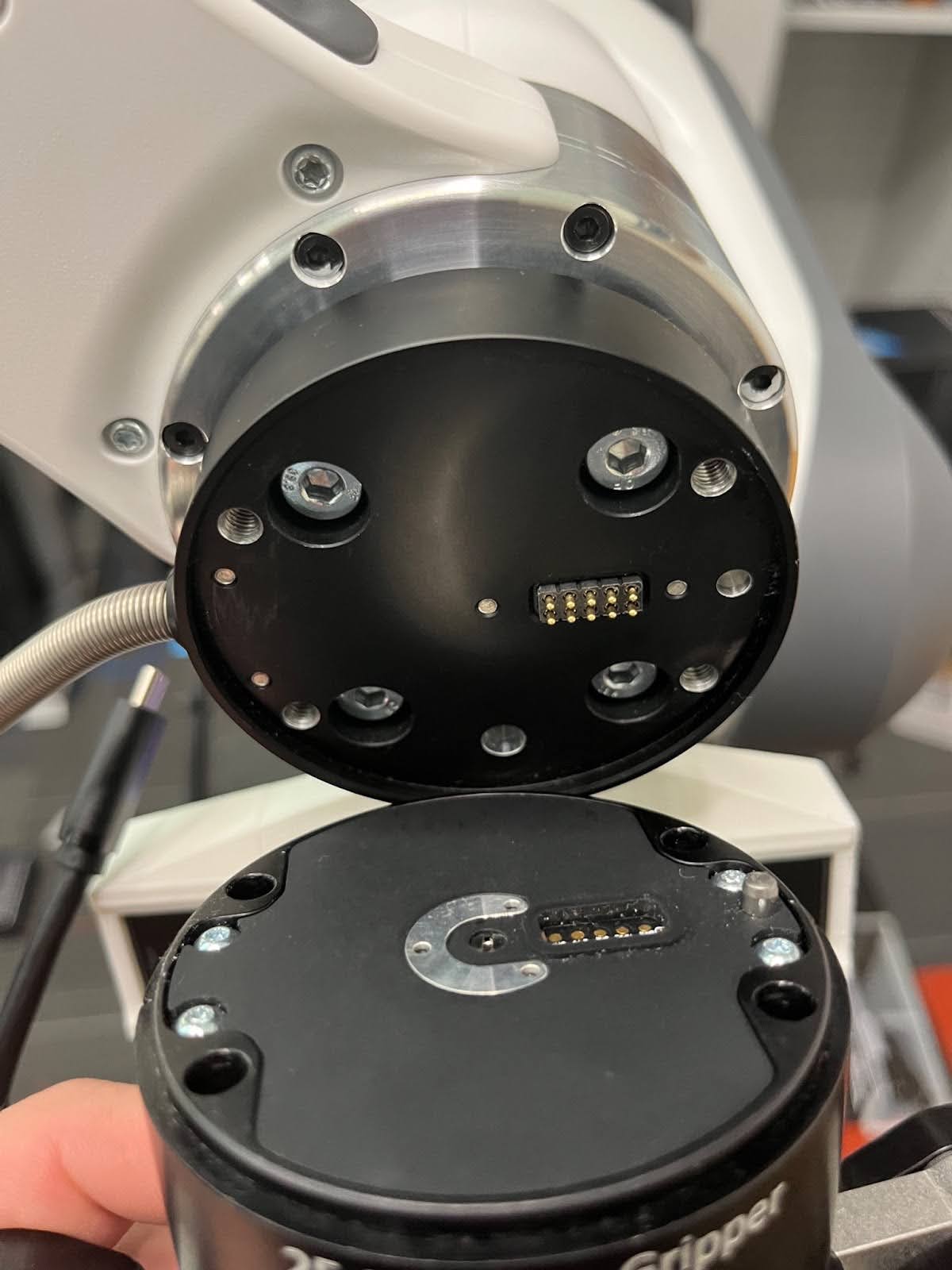
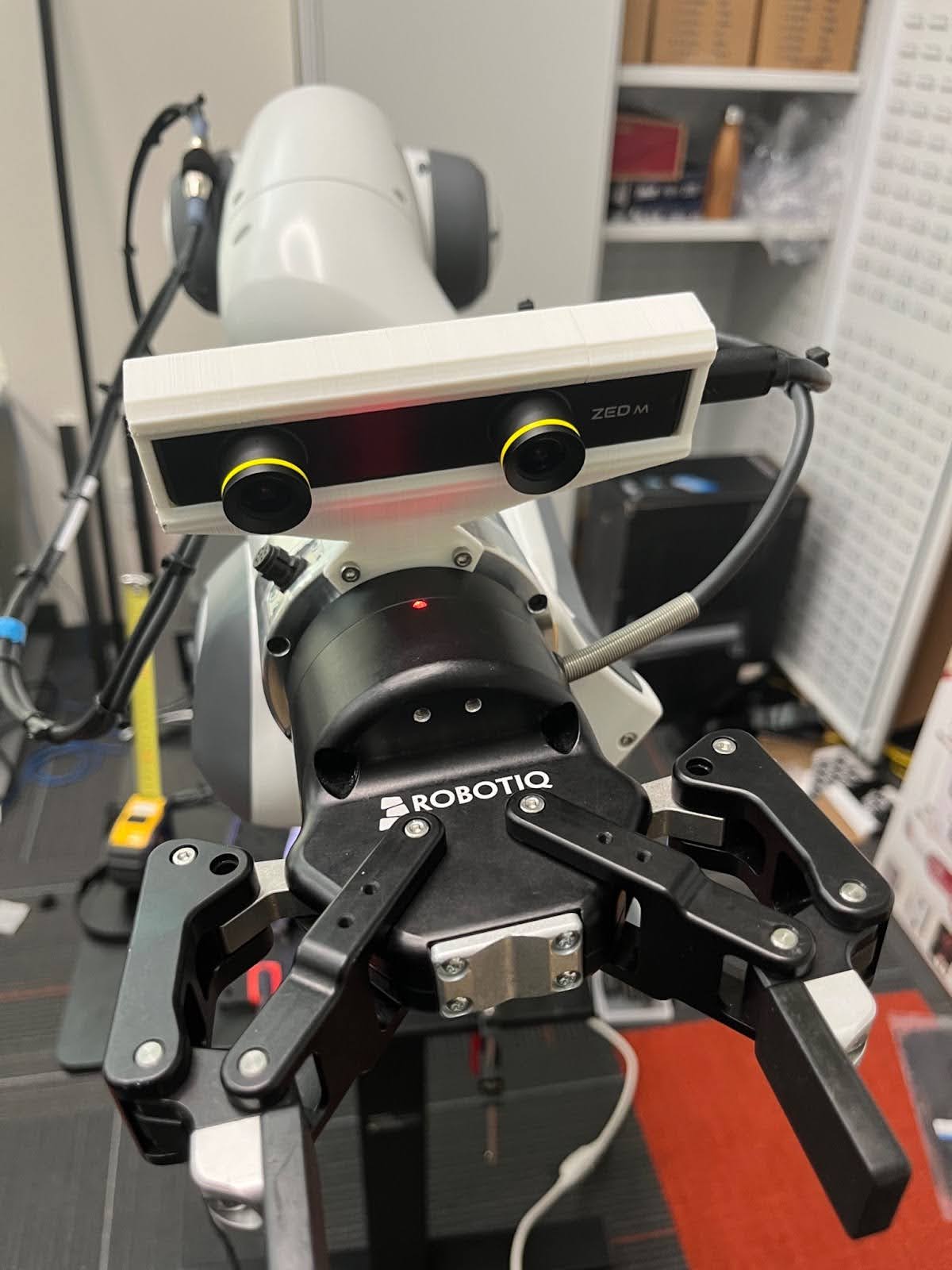
- Align the gripper mount with the screw holes on the Franka wrist, with the protruding wiring facing the right of the robot. The USB port on the camera should be facing the same direction and parallel to the protruding wire.
- Use the four smaller screws to connect the gripper mount to the Franka wrist.
- Align the Robotiq gripper with the metal pins on the wrist mount similar to the picture above. Then, use the long screws to attach the gripper in all four corners.
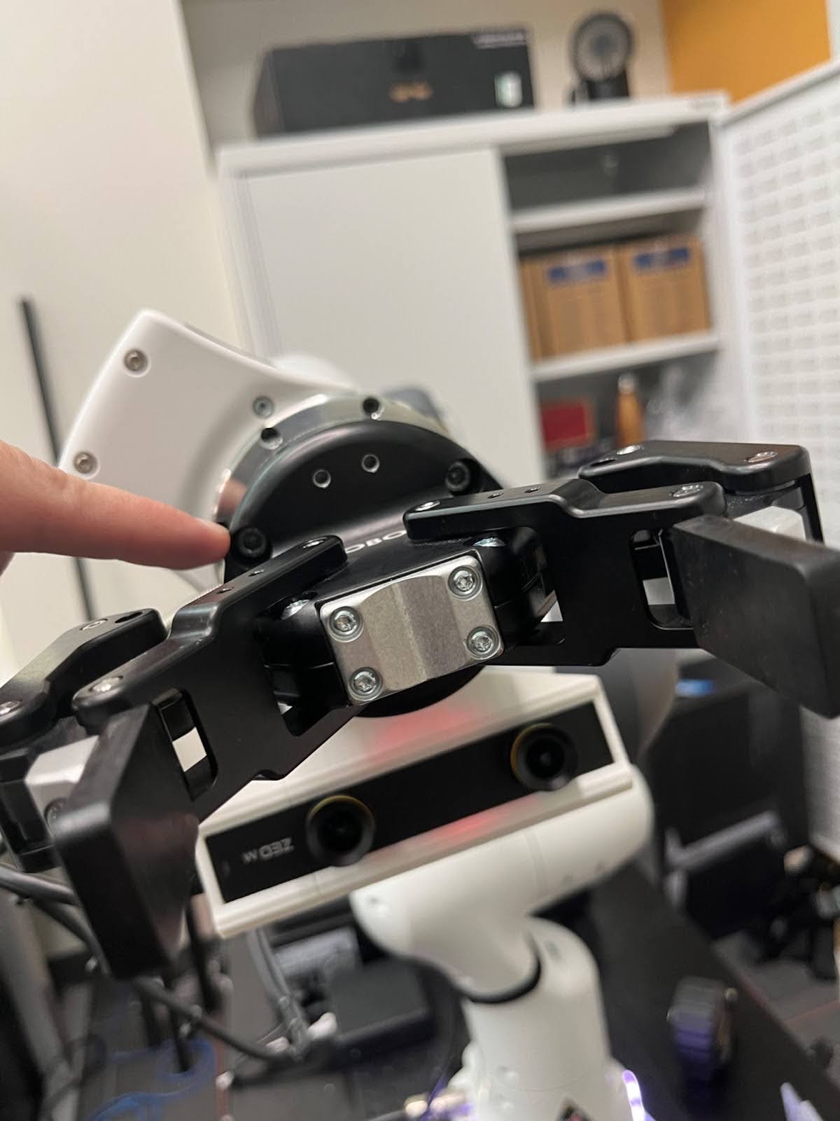
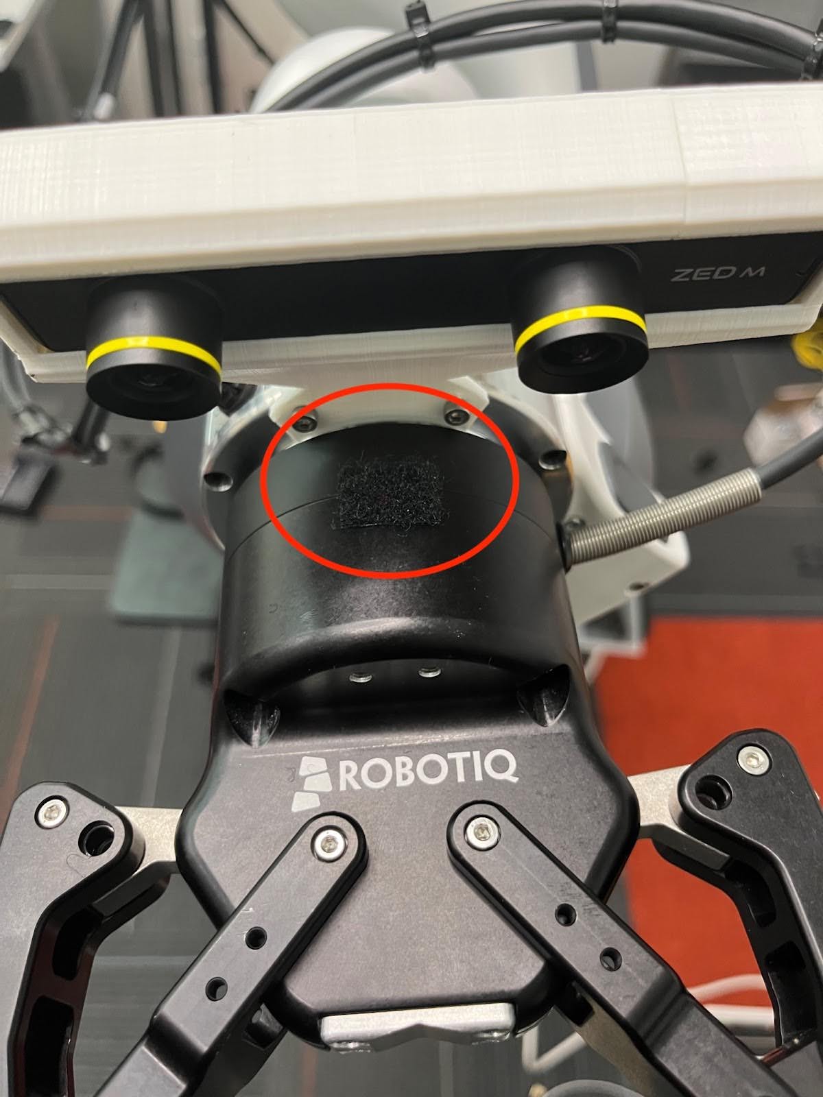
- Place a small piece of thick Velcro (soft side) over the light on the gripper. Otherwise, it will shine into the camera.
- Important: Gripper is rotated 180 degrees in the below for better view.
Robot Cable Management
In this section, we will outline how to manage cables on the Franka robot arm. You’ll want to put the Franka robot arm into zero gravity mode for this section. It is also strongly recommended that you use the 12 foot Zed Mini wire that came with the camera.
Throughout this section we’ll be strapping the wires to the robot with the velcro strips. Use the best length for each connection, and be aware that for some connections you may need to connect two strips together:
It’s important to keep the following points in mind as we work through this section:
- Leave enough slack between each wire-to-robot connection for any possible joint configuration. Joint limits are frequently reached, so make sure you do this CAREFULLY and TEST to make sure there’s enough slack meticulously! Otherwise you could damage the equipment.
- Keep the wires organized. We do not want them catching onto things during data collection!
- When you strap the Velcro straps, strap them as tight as possible! You also may want to put zip ties on either side of the wire to keep it from slipping around. Otherwise, you will compromise the amount of slack you allotted each joint.
- After you attach each strap, you may want to move the robot around to extreme positions to make sure there’s never tension on the wire.
-
As you move along the wire, use zip ties about every 5cm!
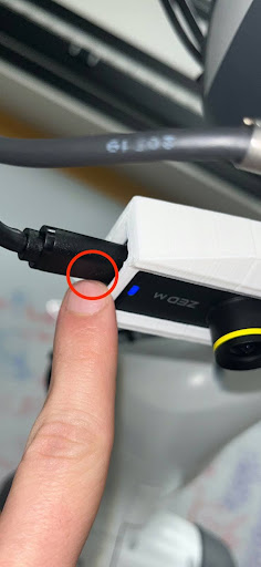
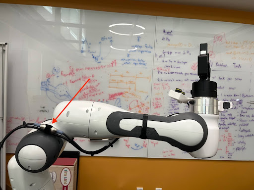
- When you plug in the camera wire, make sure:
- You use the long Zed wire that came with it! Other wires will not support fast enough data transfer.
- When plugging the wire into the camera the side with the arrow MUST face the side with the lenses. Otherwise you will get a segmentation fault when reading the camera, even though it is a USB C connection and plugs in either way!
- It’s a bit hard to see the arrows in the pictures below, but if you look at the ZED Mini wire in real life you’ll see what I am pointing at.
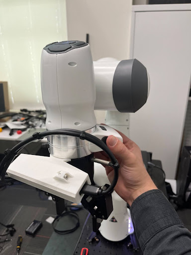
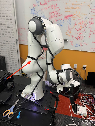
- Follow the pictures below to see the joint positions to move to before adding a tight velcro strap at the specified location.
- First picture is to visualize the neutral joint position, second picture is the extreme joint position that we need enough slack for, third picture is the wire velcro strapped with enough slack for that extreme joint position.

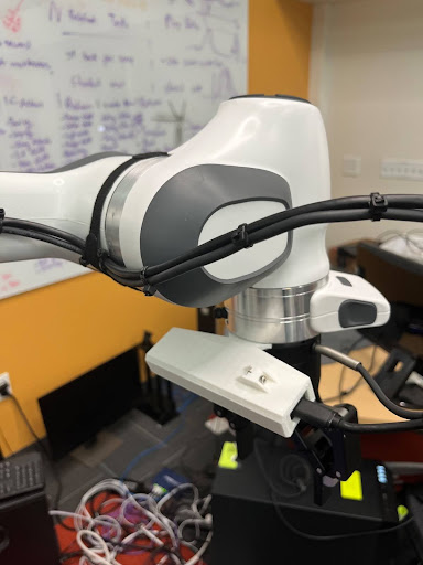
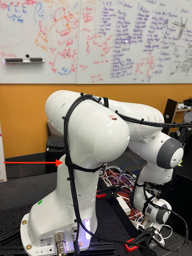
- This second velcro strap is just to manage loose wire along a joint.
- Visualization of the second joint extreme, and the next velcro strap location.
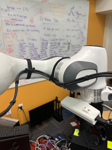
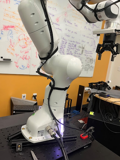
- Visualization of the third joint extreme, and the next velcro strap location.
- Visualization of the fourth joint extreme, and the next velcro strap location.
- Visualization of the final wiring:
- Now, we will connect these wires to the rest of the mobile base.
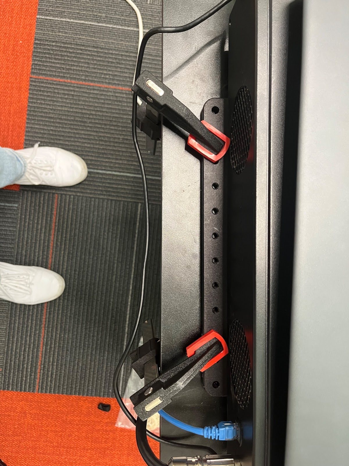
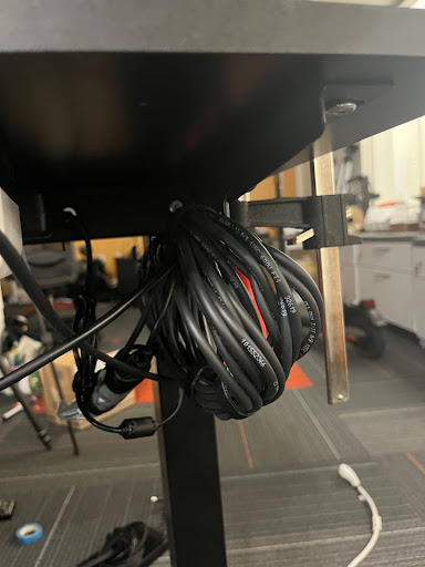
- Organize the Robotiq wire slack left over under the desk. If you bought our suggested desk, you can use the wire holders that came with the desk to hold the slack:
- Plug in the AC adapter to the power slot you left open in the Robotiq Gripper Cable Management section.
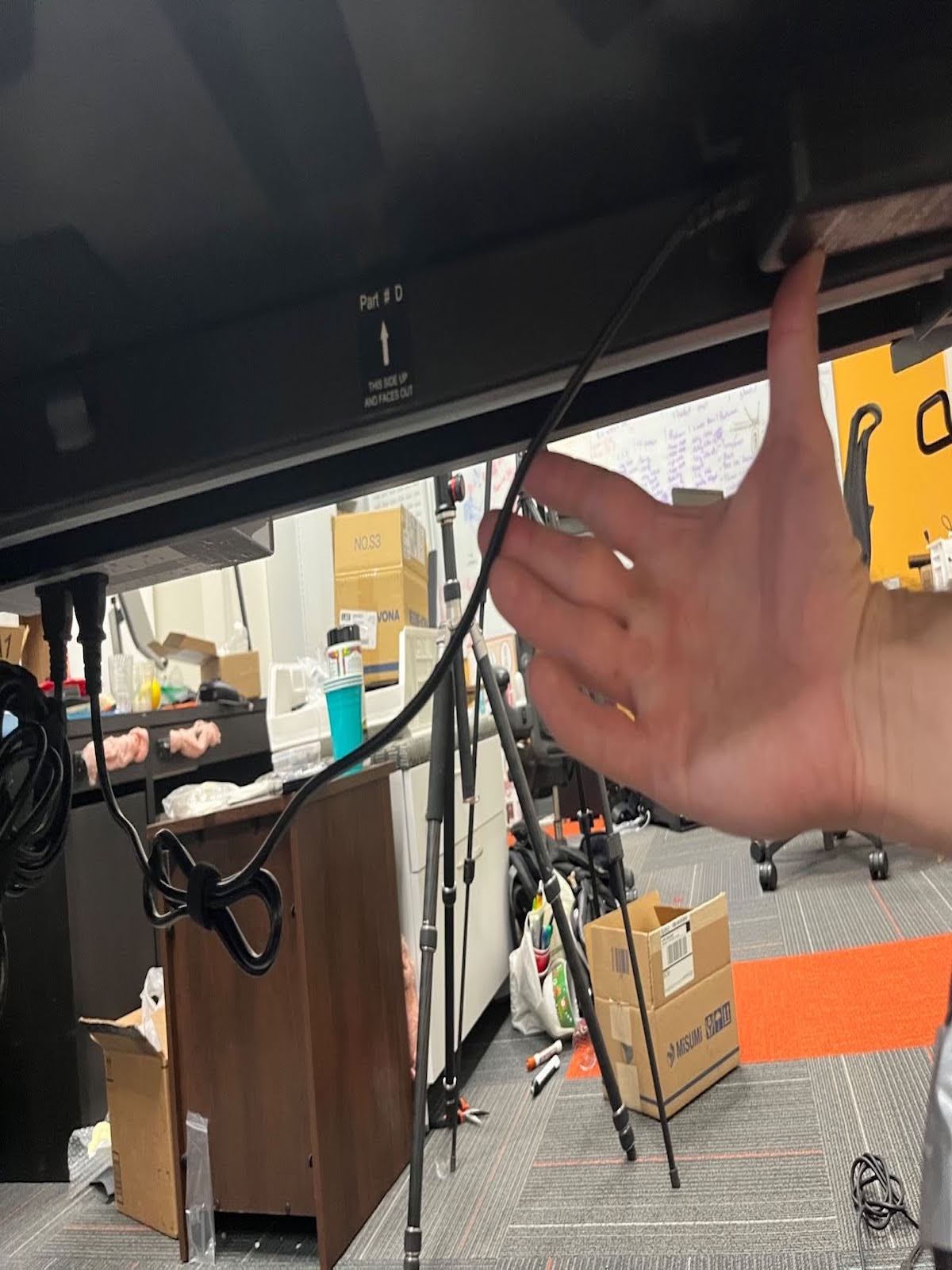
- Organize the Zed Mini wire under the desk, so it only protrudes near the laptop as follows:
Mounting Third-Person Cameras
In this section, we will clamp mounts for third-person cameras to desk.
- Clamp a camera stand to either side of the desk such that the camera attached to the stand can be positioned with a view of the scene. Take the following additional points into consideration when clamping the stand to the desk.
- The clamp and camera position of the stands should be randomized as much as possible during data collection. Don’t fix the stand to a single position each time.
- The robot arm can shake the table slightly as it moves. Whenever setting up the camera stand, tighten the clamp and all joints as much as possible to prevent the camera from shaking.
General Electrical Wiring
Power Cable Wiring
Ethernet Cable Wiring
Camera Wiring
- To keep the Alienware laptop PCI boards from getting overloaded, it is important to connect the cameras in a very specific manner. Otherwise, you will get a Segmentation Fault.
- Plug all cameras directly into the laptop ports, without the use of any Many2One USB converters OR extension chords!
- In other words, directly plug two cameras in through the USB ports on the right side of the computer, and one directly in through the usb port on the back side of the computer.
- This should leave one USB-C port open for the oculus wiring.
Mounting Calibration Board
In this section we will outline how to mount the calibration board.
Option 1: Using Magnets
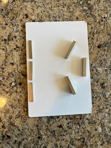
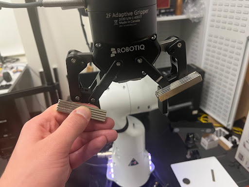
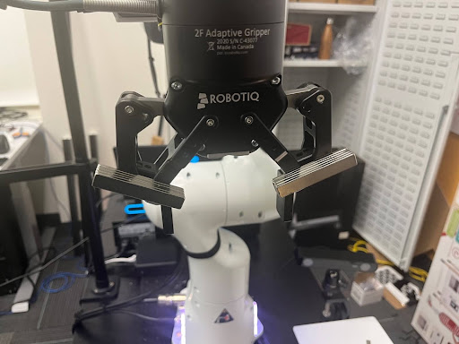
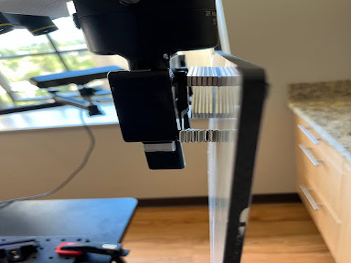
- Split long magnets into three groups of 6 stacked magnets, and put a sticky tab (provided with them) on both magnet stacks.
- Attach either (NOT THE STICKY SIDE!) to the gripper, aligning them along the metal screws as visualized below (again, the sticky side should be pointing away from the gripper!), and additionally one of the two . Be careful to evenly space the magnets so the screws are in the middle.
- Important: Sticky adhesive not visualized in this photo
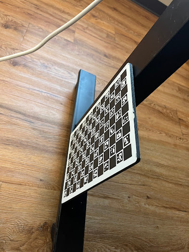
- Firmly press the Charuco board into the sticky side of the magnets, and hold it there for 30 seconds.
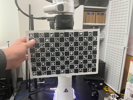
- Try moving the gripper around manually to make sure the board stays on during movement.
- Important: The board dents easily. Always be very careful not to drop it.
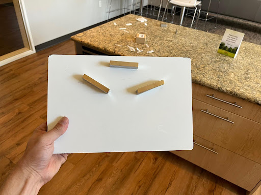
- During data collection, you can stick the charuco board to the standing desk (for transportation) using the magnets.
- Optionally, place 3 singular magnets in sequence near the other end of the board. This can be used to stick the board to the leg of the standing desk during transportation.